Toolbox Basics
Crestron's Toolbox software is vital to starting up any Crestron lighting control job. The intent of this article is to familiarize a new lighting control tech with the very basics of the various Tools available within the Crestron Toolbox software; detailed information can be access anytime from within Toolbox by pressing the F1 function key to open the Crestron Toolbox Help Menu. If a tool window is the active window, pressing F1 will open the Crestron Toolbox Help Menu to the specific page for that tool.
Initial Toolbox Configuration
When you first open Toolbox, there are several settings and preferences that Chief Integrations recommends making:
- From the list of options at the top, navigate to "File>Preferences..."
- For "Load Workspace on startup?" select "None"
- For "Save Workspace on exit?" select "Never"
- For "Automatically Connect to:" select "Nothing"
- From the list of options at the top, navigate to "Tools>Manage Tools..."
- We recommend selecting the most commonly used tools and familiarizing yourself with their icons:
 System Info
 Text Console
 SIMPL Debugger
 Script Manager
 Package Update Tool
 Network Device Tree View
 File Manager
 Device Discovery Tool
 DALI Commissioning Tool
 Network Analyzer
- Once checked, these icons appear as shortcuts below the "File/View/Tools/etc." menus
- We recommend selecting the most commonly used tools and familiarizing yourself with their icons:
Connecting to Devices
In order to connect to any lighting devices, your computer must be physically connected to the lighting device or the lighting network. Typically, this is achieved via TCP (i.e. Ethernet or WiFi) or USB (usually a USB-A to USB-B cable), though some older devices may require an RS-232 serial connection or a different USB cable. Devices with authentication enabled (such as any 4-Series processor, RF/Zūm Wireless Gateway, etc.) will require credentials to be configured upon initially connecting to the device and then those credentials will be required when connecting in the future. It is imperative that the Crestron Agent or Field Tech saves these credentials. Chief Integrations cannot assist without being able to connect to the device. The only way to connect to a device for which the credentials have been lost is to factory reset the device, which may require redoing the start-up from scratch.
Any Toolbox tool which requires connecting to a device has several buttons and fields at the lower left which relate to device connection:

These elements have various functions:
- Address Book Menu - Used to view and edit the current address book, or to change the active Address Book to a different Address Book. See Troubleshooting a Failed Connection below for information about creating an Address Book
- Known Device Dropdown - This drop down menu can also be used to connect to devices in the current Address Book. If the currently connected device is in the Address Book, it's name in the Address Book will be displayed here
- Manual Connection Menu - This menu is used to manually connect to a device that is not in the current Address Book. It can be used regardless of the connection type or device being connected to:
- Quick Function Menu (keyboard shortcut: ALT+F) - menu containing a few useful functions
- Firmware (keyboard shortcut: ALT+O) - menu for loading firmware
- SIMPL Program (keyboard shortcut: ALT+P) - menu for loading a SIMPL or SIMPL# Program
- Project (keyboard shortcut: ALT+T) - menu for loading an XPanel UI
- Current connection status ("Connecting", "Connected", "Disconnected", or "Unknown")
- Current connection type and address (e.g. "usb" or "ssh 10.44.5.71")
USB Connection
Connecting to a device via USB is only recommended during initial configuration of the device's IP settings or if there is an issue with connecting via Ethernet/TCP. The data transfer rate over USB is very low relative to Ethernet, and so any activities that require data transfer (such as updating firmware, updating showrunner™, or loading a UI) will take much longer than necessary. Additionally, when connecting via USB, only the device you are plugged in to will be connectable in Toolbox, rather than being able to connect to any device on the lighting network as would be possible when connected by Ethernet.
To connect via USB:
- Determine the necessary USB cable
- Most devices (DIN-AP3, DIN-AP4, DIN-CENCN-2, etc.) will require a USB-B connection, but some devices may require a Mini USB-B or Micro USB-B connection
- Plug the USB cable in to both the device and your computer
- Open Toolbox and then open the desired tool
- Connect to the device
- If you are using the Default Address Book, there is already an entry for "Local-USB"
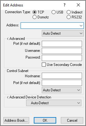
- If you are not using an Address Book, then you should click the Pencil Icon to open the Manual Connection Menu:
- Change the connection type from "TCP" to "USB"
- Leave Model, Hostname, and Serial fields blank
- If the device has authentication enabled, expand the Advanced options and input the username and password
- Click "OK"
- The current connection status field should change from "Unknown" to "Connecting"
- After a brief period, the connection status field should change from "Connecting" to "Connected"
- Some devices may take longer than others to connect
- If the device has just recently powered up, it may take a few minutes to completely wake up before it can be connected to
- If you have issues connecting, see Troubleshooting a Failed Connection below
Ethernet Connection
Plugging in to the lighting network and connecting to devices via Ethernet is the most useful way to connect to lighting control hardware. When your laptop is connected to the lighting network, you are able to connect to any device that is on the network, as well as connect to multiple devices simultaneously. Unlike with a USB connection, connecting to a device via Ethernet does not require physical proximity to the device. Wireless connection to the lighting network is possible if the lighting network has properly configured a wireless router on it.
To connect to a device via Ethernet, your laptop must first be connected to the lighting network.
To connect to the lighting network:
- Identify an open where you are able to plug in to the lighting network
- Many Crestron processor and HUB panels will have one or more CEN-SW-POE-5 or CEN-SWPOE-16 ethernet switches. Any open port on these Ethernet switches should be able to be used to connect a laptop to the network.
- Laptops do not require power over Ethernet, so it is acceptable to use the "Uplink" port if necessary.
- If the lighting network is on the building LAN, then you may need to reach out to the building's IT department for instructions on how to access the lighting network or VLAN.
- Use a Cat 5a or Cat 6 cable to connect your laptop to the lighting network at an open port
- Most newer laptops will require some sort of adapter in order to connect to a Cat 5a/6 cable
- Configure your laptop's network settings (FAQ page) to be compatible with the lighting network:
- Navigate to Control Panel>Network and Internet>Network Connections
- Locate the network adapter that is connected to the lighting network
- Right click the network adapter and click "Properties"
- In the Networking tab of the adapter Properties menu, select "Internet Protocol Version 4 (TCP/IPv4)" from the list
- Click the "Properties" button
- If the lighting network uses static IP addresses:
- Click "Use the following IP address:"
- For the IP Address, give your laptop an address that is in the range of the lighting devices but that does not conflict with any addresses on the network
- For the Subnet mask, give your laptop the same subnet mask as the lighting devices
- The Default gateway can be left blank
- Once all settings have been configured, press "OK" to close the IP configuration dialog
- E.g., if there is a lighting network with a processor at 10.0.0.10, a DIN-CENCN-2 at 10.0.0.11, and a TSW at 10.0.0.12 and all devices have a subnet mask of 255.255.255.0, then your laptop can have any address in the range 10.0.0.2 through 10.0.0.9 or 10.0.0.13 through 10.0.0.254, since these addresses are all in the subnetwork range and are not being used by other devices.
- Press "OK" again to close the Ethernet Properties dialog
- If the lighting network has a DHCP server (such as a CP4N control subnet):
- Use the "Obtain an IP address automatically" option
- Press "OK" to close the IP Configuration dialog
- Press "OK" again to close the Ethernet Properties dialog
- Your laptop will automatically be assigned an IP address in the correct range by the DHCP server on the network.
- You can verify this by opening the Windows Command Line tool and running "ipconfig" command to view your current adapter settings
- If the lighting network uses static IP addresses:
- Open Toolbox and then open the desired tool
- Connect to the device:
- If you have created an address book (see Export to Address Book below), then select the device from the drop down menu
- If you have not created an address book, then you should click the Pencil Icon to open the Manual Connection Menu:
- Leave the connection type as "TCP"
- Type in the IP address or Hostname of the device you wish to connect to
- Generally, the "Auto Detect" box should be left at "Auto Detect", though if you know what type of connection you need then you can manually change it
- CEN-GWEXERs with Authentication enabled require manually setting the connection type to "TSL/SSL"
- Leave Model, Hostname, and Serial fields blank
- If the device has authentication enabled, expand the Advanced options and input the username and password
- Click "OK"
- The current connection status field should change from "Unknown" to "Connecting"
- After a brief period, the connection status field should change from "Connecting" to "Connected"
- Some devices may take longer than others to connect
- If the device has just recently powered up, it may take a few minutes to completely wake up before it can be connected to
- If you have issues connecting, see Troubleshooting a Failed Connection below
Troubleshooting a Failed Connection
Sometimes, a connection attempt will fail and you will need to do some troubleshooting to figure out why exactly the connection could not be established. Toolbox will give different error messages, though sometimes it can be helpful to attempt to connect with another software such as PuTTY just in case the error message is more informative from the alternate software.
"Device refused to identify"
- This message typically means that the device is not online or could not be connected to
- This message may also occur when a device has blocked your username or IP address due to making too many incorrect login attempts
- IP addresses are blocked for 24 hours by default, but you can attempt to circumvent this block by changing your IP address and trying again
- Users are blocked for 30 minutes by default, and it is only possible to circumvent this if another user has already been created, otherwise you must wait for the block to expire before connecting again
- The below commands are useful if you are able to connect to the processor through some other means (specific commands may vary depending on the device):
- listblockedip and remblockedip commands can be used to view/unblock an IP address
- listlockeduser and remlockeduser commands can be used to view/unblock specific users
- setloginattempts and setlockouttime commands can be used to modify how many login attempts are allowed before blocking an IP address and how long an address will be blocked
- setuserloginattempts and setuserlockouttime commands are used to modify how many login attempts are allowed before blocking a user and how long that user will be blocked
- setlogoffidletime command can be used to modify how long you can be inactive before the processor automatically logs you out
"Device not found in database"
- This message typically means that the version of your device database is out of date and the device being connected to is not in it. Use Crestron's MasterInstaller tool to ensure that Toolbox and all installed Crestron components are up-to-date
See our FAQ for additional tips:
Basic Tool Usage
Crestron Toolbox has many tools that are essential for starting up or troubleshooting any ShowRunnerCLC™ installation. The tools covered here are the most commonly used in commercial lighting contexts, but it should be noted that this list is by no means exhaustive. If you have many Tool windows open at once in Toolbox, or if you have only a few Tools open but the window is maximized, then the Window dropdown menu at the top of Toolbox will be useful for navigating the open tools. The Window dropdown has options for cascading/tiling all open tools, as well as a list of open windows to allow easily switching between them: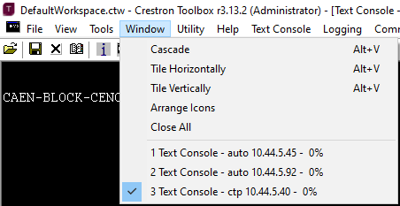
Device Discovery Tool
Crestron's Device Discovery Tool is used to "discover" any Crestron devices which are connected to your laptop. The most useful feature of the Device Discovery Tool is the ability to export all discovered devices to either a "Device Summary" text file or an Address Book. Discovered devices are listed in a scrollable list on the left side of the menu, and double clicking a discovered device will bring up additional configuration options on the right side. Below is an overview of the Device Discovery Tool UI:
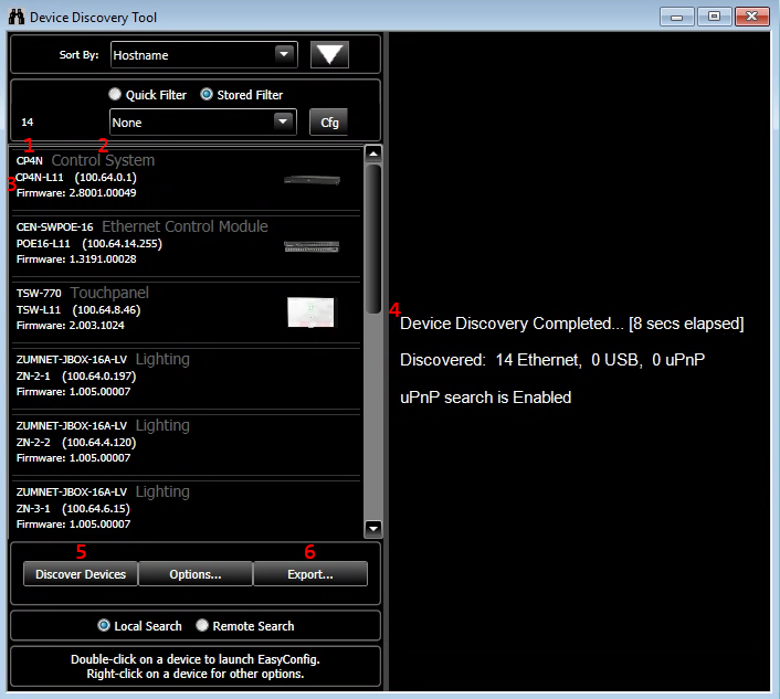
- Device Model - gives the specific model of the device type
- Device Type - gives an idea of what function the device serves ("Control System", "AV", "Lighting", etc.)
- Connection and Firmware Information
- Ethernet connected devices give their hostname, IP address, and firmware version
- USB connected devices give their hostname, serial number, and firmware version
- Discovery Summary - gives a summary of how long it took to discover devices and how many devices were discovered at each connection type
- Discover Devices button - press this to restart the discovery process
- Export... button - use this button to export discovered devices to either a Device Summary or Address Book (covered in more detail below)
Local vs Remote Search
When using your laptop to do a Device Discovery, the default option for where to search for Crestron devices is "Local Search". This means that you will only be able to detect devices that are directly on same network as your laptop, even if communication between your laptop and the device is allowed in the network configuration. In these cases it can be useful to do a "Remote Search", which allows the Device Discovery to be performed from a Crestron device that is on a separate network from your laptop. Remote Search can also be done when connected to a device via USB, which makes it useful in situations where there are no open Ethernet ports or where the technician's laptop is not authorized to connect to the LAN.
To do a remote search:
- Open Device Discovery Tool as normal
- Wait for the initial Local Search to conclude
- Press the button at the bottom of Device Discovery Tool window to select Remote Search
- In the connection bar that should appear at the bottom of the Device Discovery Tool window, use the pencil icon to input the details of the device you want to use for the search
- Any 3-Series and 4-Series processor can be used to perform a remote search, but some devices (such as CEN-GWEXERs and DIN-CENCN-2s) will not work
- Wait for the Remote Search to conclude
The below screenshot compares the results of a Local Search from a laptop that is on a 10.44.2.0/24 VLAN to the results of a remote search performed by a processor that is on a 10.44.5.0/24 LAN. Even though the network is configured to allow the laptop on the 10.44.2.0/24 network to connect directly to the processor at 10.44.5.45 on the 10.44.5.0/24 network, we are not able to discover any of the devices on that network when performing a Local Search (left window). When we use the processor for the Remote Search (right window), we are able to discover all 35 devices on t he 10.44.5.0/24 network. 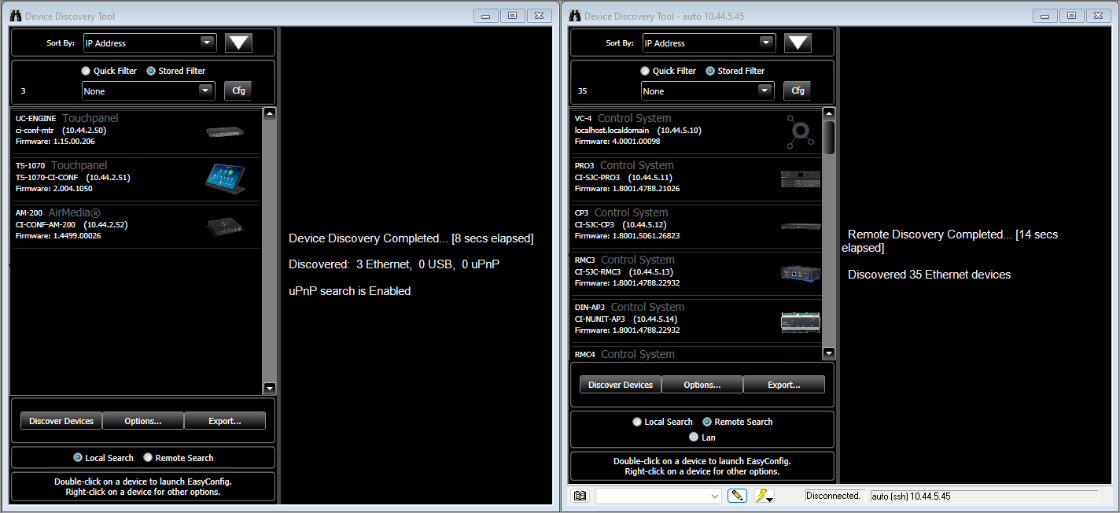
Export to Address Book
Address Books  provide a convenient way to easily connect to different devices without memorizing all the different IP addresses and credentials for devices on your network. When an Address Book has been created for a job, you are able to connect to specific devices using the dropdown menu on the lower left of the tool instead of manually inputting the IP address or hostname using the Pencil menu. Note that when exporting devices to the Address Book, it is possible to add devices by either Hostname or by IP Address, and if the device settings are modified then it may be necessary to update your Address Book or create a new one.
To create an Address Book in Toolbox:
- Connect to the lighting network and open Device Discovery Tool in Toolbox
- The Device Discovery tool will automatically report how many Ethernet devices have been discovered
- Verify that the expected number of Ethernet devices have been discovered, including any TSWs, GLPACs, DIN-CENCN-2s, etc.
- Note that only Crestron devices will appear in Device Discovery; non-Crestron devices (such as Pharos or Enttec DMX controllers) will not appear in Device Discovery Tool
- If no devices are discovered, verify that your computer is connected to the network and your IP address is compatible with the network
- If some devices are missing and you are not filtering the results, then there may be an issue with your DHCP server settings or the network wiring
- Click the "Export..." button below the list of discovered devices
- If this button says "Address Book", then Toolbox needs to be updated
- Ensure that you are not filtering out any devices or that you have only filtered out the devices you want to be filtered out
- Select how you would like devices to be saved:
- Hostname - Recommended for jobs with DHCP servers, though it should be noted that the Address Book must be updated if device hostnames are changed; entries are named with the device hostname by default
- IP Address - Recommended for jobs with static IP addresses only; entries are named the form "[hostname]_ip" by default
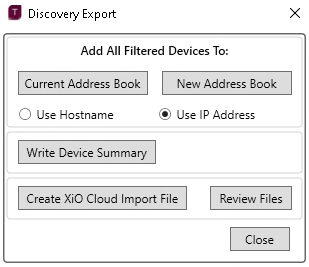
- Click the "New Address Book" button to create a new Address Book with these device
- Click the "Current Address Book" button to add devices to the currently active Address Book; note that if an Address Book has just been created but not has not yet been made the active address book, then devices will not be added to that Address Book (more likely they will be added to the "Default" address book instead)
- Devices with the same name and connection method will be overwritten, while devices with new names will be added
Once a new Address Book has been created, it must be manually selected and made the current Address Book before the new devices will appear in the connection dropdown menu
- Open any tool and click the Address Book Menu button on the lower left, or open the Address Book dialog directly from the Tools > Manage Address Book...
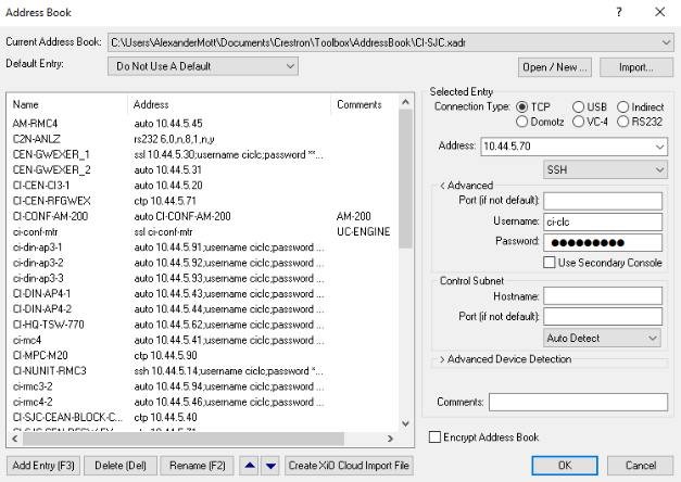
- The currently selected address book is displayed in the "Current Address Book" field, and recently opened Address Books are available in the dropdown menu
- To open an Address Book that has never been open or has not recently been opened, click "Open / New..." and locate the Address Book
- By default, newly created Address Books are saved to your "Documents\Crestron\Toolbox\AddressBook\" folder
- Click the "Open" button to make the selected Address Book active
- If desired, the "Name" or "Address" column headers can be clicked to change the order devices are displayed in the dropdown menu
- The up and down arrows at the bottom of the menu can be used to manually re-order devices
- Connection settings for individual entries in the Address Book can be modified by selecting them and then editing their attributes in the menu on the left, including:
- Connection type (TCP, USB, etc.) and method (SSH, SSL/TLS, etc.)
- Connection port
- Credentials
- Right-click on an entry to rename or delete it, or select the entry and use the buttons at the bottom of the menu
- Click "OK" without selecting a device from the list to close the Address Book dialog without connecting to a device, or select a device from the list and click "OK" to connect immediately
Export to Device Summary
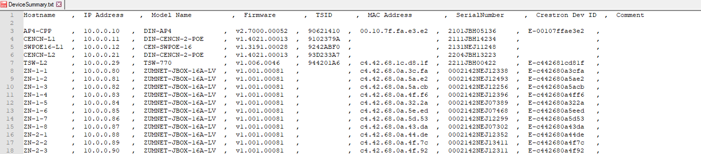
The Device Summary is an important documentation tool provided by Crestron. It is a .txt file containing a comma-separated-values of all networked devices, and is useful to capture which devices are online, what their current IP and hostname settings are, what version of firmware they are on, and their MAC address and serial number.
To generate a Device Summary in Toolbox:
- Connect to the lighting network and open Device Discovery Tool in Toolbox
- The Device Discovery tool will automatically report how many Ethernet devices have been discovered
- Verify that the expected number of Ethernet devices have been discovered, including any TSWs, GLPACs, DIN-CENCN-2s, etc.
- Note that only Crestron devices will appear in Device Discovery; non-Crestron devices (such as Pharos or Enttec DMX controllers) will not appear in Device Discovery Tool
- If no devices are discovered, verify that your computer is connected to the network and your IP address is compatible with the network
- If some devices are missing and you are not filtering the results, then there may be an issue with your DHCP server settings or the network wiring
- Click the "Export..." button below the list of discovered devices
- If this button says "Address Book", then Toolbox needs to be updated
- Ensure that you are not filtering out any devices or that you have only filtered out the devices you want to be filtered out
- Click the Write Device Summary button and save the Device Summary to your computer
- Though saved as a text file, the Device Summary is actually a table of comma separated values
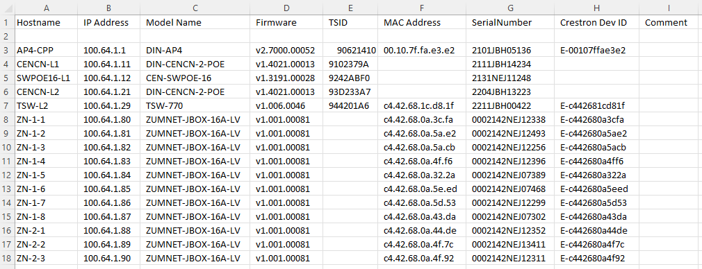
- Renaming DeviceSummary.txt to DeviceSummary.csv will allow it to be opened and manipulated in common spreadsheet software such as Microsoft Excel or LibreOffice Calc
- Note that this .csv will have whitespace, so you may want to "clean" it using Excel's "=TRIM()" function if you intend to copy/paste it into the takeoff
Below is an example of a Device Summary for a fully-configured Zūm Wired job:
- DeviceSummary.txt:
- DeviceSummary.csv:
Text Console
Text Console is one of the most important tools in the Crestron Toolbox. Whenever the Chief Integrations' ShowRunnerCLC™ Startup Guide mentions "sending console commands," the Text Console is the tool that is required. Below are some general tips that may come in handy when using the Text Console tool:
- It recommended to run the command broadcast on as the first command when connecting to a processor, as not running this command means that you will miss important messages from the device
- The Text Console buffer (all commands and messages from the current Text Console session) can be saved and exported to .txt and .tblog files by using the "Logging > Save Buffer..." menu above the toolbar
- The Text Console buffer is not infinite, and will fill up if a large number of messages are sent and received (indicated by the percentage given in the Text Console window)
- Pressing alt-c or right-clicking and selecting "Clear" will clear the Text Console buffer and make it easier to navigate through recent messages
- Pressing the up arrow key on your keyboard will cycle through recently sent commands, and pressing tab when a specific command is highlighted will allow you to edit the command before sending it
- Commands are generally not case sensitive with the exception of commands relating to credentials (i.e. a user's password) and some specific commands as noted in this guide
Below are some generally useful console commands for Crestron devices. Note that while most or all Crestron devices will allow for a Text Console connection, only processors with a running and licensed copy of the ShowRunnerCLC™ software will allow the use of the ShowRunner™ specific "sr" commands. Text Console commands for specific tasks/functions required by ShowRunnerCLC™ are covered in more detail on the pages that cover those tasks, but the below commands are generally useful for a variety of tasks:
- It recommended to run the command broadcast on as the first command when connecting to a processor, as not running this command means that you will miss important messages from the device
- Use the help all or hidhelp all commands to list all available Crestron-specific commands available (i.e. commands that are available regardless of whether the ShowRunnerCLC™ program is running on the processor)
- Use sr ? and sradmin ? commands to view all ShowRunnerCLC™ specific commands available
- These help lists can be further refined by typing out more of the specific command you want to learn about, e.g. sr devmgr ? will show commands related to the ShowRunnerCLC™ device manager
- Use err sys command to show the error log (up to the last 500 entries), and use the clear err command to clear the log (useful if you are about to restart the program to diagnose errors and don't want to need to sort through which errors are new and which are from the previous startup)
- Many commands can be shortened by typing just enough letters to make the command unique, e.g. sr show loads can be shortened to sr sh lo and setlogoffidletime can be shortened to setl
- See our ShowRunnerCLC™ Command Line Interface and Debug Program Logic pages for more information on ShowRunnerCLC™ specific commands, or see our Frequently Used Crestron Commands page for built-in Crestron commands
File Manager
File Manager is an essential tool for transferring files to and from the processor. While the ShowRunnerCLC™ license and configuration files can be loaded through the ShowRunnerHUB™ Web UI, it is still sometimes necessary to use the File Manager tool in certain circumstances (e.g., an Ethernet connection to the device cannot be established or for transferring files that aren't supported through the Web UI, such as custom ShowRunner™ extensions).
To use File Manager:
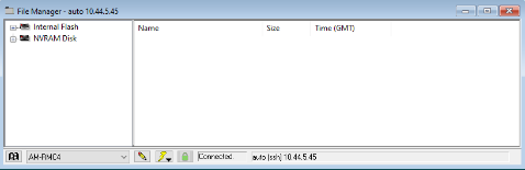
- Open the File Manager tool and connect to your device
- Note that not all devices have accessible storage, so File Manager tool will not always connect even if the device is online
- Note that not all devices have accessible storage, so File Manager tool will not always connect even if the device is online
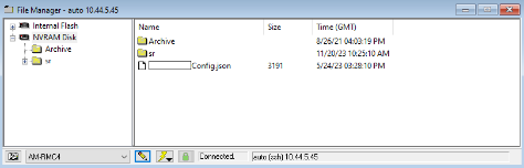
- Navigate your device's storage using either the navigation bar on the left or by double-clicking into folders on the right
- Note that some older versions of Toolbox only allow navigation using the navigation bar on the left
- Note that some older versions of Toolbox only allow navigation using the navigation bar on the left
- Once you've navigated to the directory that you want to add files to or remove files from
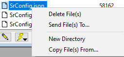
- Copy files to the current directory by either dragging the file from your computer into the File Manager tool or by right-clicking on an empty space and selecting "Copy File(s) From...":

- Copy files from the device ("Send File(s) To...") to your computer or modify files on the device by right-clicking on the file:
- Copy files to the current directory by either dragging the file from your computer into the File Manager tool or by right-clicking on an empty space and selecting "Copy File(s) From...":
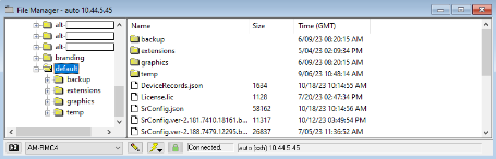
- For normal Crestron processors (i.e. not VC-4 instances), ShowRunnerCLC™ files belong in the following folders (v3.10 and newer):
- ShowRunnerCLC™ license goes into the "NVRAM/sr/" folder
- ShowRunnerCLC™ SrConfig.json configuration file goes into the "NVRAM/sr/default" folder
- Note that older releases ShowRunnerCLC™ use a different file structure
- Note that the "alt-[x]" folders are for ShowRunnerCLC's "Alternate Configuration" feature and are not present in most deployments
Network Device Tree View
Network Device Tree View is a useful tool for addressing devices and resolving certain issues with networked hardware. Below are just some general tips for using the tool; see our device addressing page for specific instructions on how to use the Network Device Tree View for device addressing. The below are some general tips and recommended settings for Network Device Tree View:
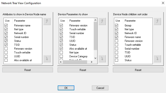
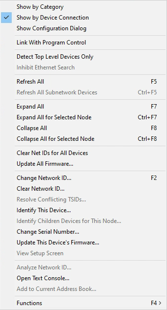
- When connecting to a device for the first time in Network Device Tree View, we recommend making certain changes to the type of information displayed by right-clicking and selecting the "Show Configuration Dialog" option:
- Displaying the Serial Number and TSID is useful for easily identifying devices and determining whether specific devices are online or not
- Displaying the Network ID is useful for easily identifying whether devices have been addressed or not
- Displaying the Net Type is somewhat optional, as it should be apparent whether devices are connected via Cresnet, zummesh, etc. based on the model of device
- Displaying Status is also optional, as this information is also displayed in the form of a colored icon next to the device model
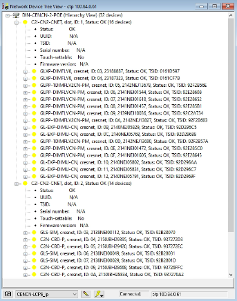
- In addition to the above settings, it is generally recommended to right-click and ensure that "Show by Device Connection" is checked
- "Show by Device Connection" will group devices by their connection to the host device (e.g., Cresnet devices on a DIN-CENCN-2 will be sorted by the Net that they are connected to, Zūm Wireless devices will be sorted by the ZUM-NETBRIDGE they are connected to, etc.)
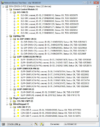
- "Show by Category" can be useful in some situations, particularly when looking at devices on a processor where all of the devices are necessarily on the same net, but it can be confusing since you are not able to tell at a glance how a device is connected (i.e. whether it is on Net 1 or Net 2 of a DIN-CENCN-2) and may result in accidentally misaddressing devices; notice how in the below example there appear to be duplicate network IDs (e.g. a keypad and a GLXP-DIMFLV8 both at ID: 04) that aren't being flagged as duplicates because the devices are actually on different Nets, a detail that is only visible when "Show by Device Connection" is enabled as shown above.
- "Show by Device Connection" will group devices by their connection to the host device (e.g., Cresnet devices on a DIN-CENCN-2 will be sorted by the Net that they are connected to, Zūm Wireless devices will be sorted by the ZUM-NETBRIDGE they are connected to, etc.)
- These configuration changes are saved per device type, so once they are made they will not need to be made again unless you are connecting to a new type of device for the first time (e.g. changes made while connected to a DIN-AP4 will apply to all DIN-AP4s, but will not apply to any DIN-CENCN-2s you may connect to later)
- If Network Device Tree View has been configured as recommended above, then the interface will look similar to the below for a fully-addressed system with no issues:
- Since all of the devices have been addressed and there are no issues, the Network Device Tree View shows a yellow circle next to each device indicating an "OK" status
- A new system where all devices are online but have not been re-addressed may look more like the following example, with a red exclamation point indicating duplicate Network IDs
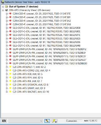
- Other types of status indicator may include a black circle for "Invalid Network ID" or "Invalid/duplicate TSID or Serial Number"
- Since all of the devices have been addressed and there are no issues, the Network Device Tree View shows a yellow circle next to each device indicating an "OK" status
- Right-clicking on an individual device will give many options to resolve common issues, as well as allow for identifying a specific device:
- "Refresh All" use to refresh the list of actively connected devices, necessary e.g. if a Cresnet cable has been connected/disconnected from the device
- F5 is the keyboard shortcut for this function, though in both cases it may be more reliable to completely close and reopen Network Device Tree View to ensure all devices are refreshed
- "Change Network ID..." use to change the Network ID (CID) of a specific device (see our device addressing page for more information)
- F2 is the keyboard shortcut for this function
- "Identify This Device..." will put a specific device into "Identify" mode, the specific behavior for which depends on the individual device:
- Note that entering identify mode may stop the ShowRunnerCLC™ program and restart it when exiting identify mode: to avoid losing progress and placing strain on the processor, it is recommended to either identify and address all hardware prior to loading the ShowRunnerCLC™ program, or temporarily suspend the program with the console command stopprog -p:01 and then resume the program once done identifying all devices with the command progreset
- Some devices will flash an LED (Cresnet keypads, GLS-SIMs, et al.)
- Some devices will flash an LED and make a noise (Cresnet occupancy sensors, most room controllers, et al.)
- Load controllers will typically flash all connected loads
- "Change Serial Number..." is used to change the device's Serial Number (and thus its TSID); this is rarely required and is only necessary in cases where a device reports an invalid or duplicate SN/TSID, or where the reported SN does not match the SN physically printed on the device
- "Open Text Console..." will open a Text Console window directly to the specific selected Cresnet/RFID device (not to the host device you are connected to in Network Device Tree View); only recommended for advanced users
- "Refresh All" use to refresh the list of actively connected devices, necessary e.g. if a Cresnet cable has been connected/disconnected from the device
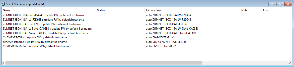
Script Manager
The Script Manager is where Load Scripts can be opened and specific sets of commands executed. Load Scripts are .txt files that allow you to automate certain tasks by connecting to a device and executing a predetermined sequence of commands, and are a powerful tool to save time on-site when you need to run the same or similar set of commands on many devices.
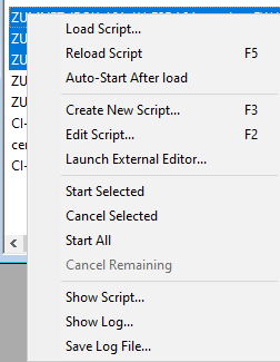
To use a Load Script with the Load Script Manager:
- Open the Load Script Manager in Toolbox
- Right-click anywhere in the Load Script Manager, select "Load Script...", and locate your Load Script .txt file
- The window will populate with all of the different command sets defined in the Load Script
- Ensure that you are connected to your devices by the method required based on the connection type listed in the "Connection" column
- This example script is expecting to connect to devices over Ethernet using their hostname
- Select the command sets you would like to execute by ctrl+clicking or shift+clicking them and then right-click and "Start Selected" to begin executing the commands
- If no commands are currently running, the "Start All" option will also be available. Note that the number of concurrent command sections may be limited by the load script, so even if "Start All" is selected there may only be e.g. 10 command sets that actually start
- If commands are currently running, you can cancel them using this right-click menu as well
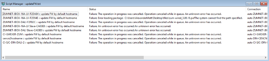
- While commands are running, their current status and progress are displayed under the various columns displayed in the Script Manager
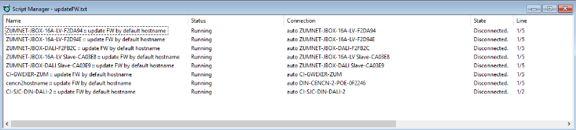
- Once a command section has executed all commands, it will display the success or failure of the commands
- In this example, all of the commands failed for different reasons:
- ZUMNET-JBOX-16A-LV-F2D94E commands failed due to the firmware file specified by the script not being in the correct location
- The commands which failed due to an "unknown error" failed because they weren't reachable at the specified connection address due to some quirks with this specific LAN configuration
- The remaining command sections were manually cancelled before they could complete
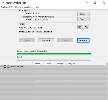
Package Update Tool
The Package Update Tool is a very convenient way of performing firmware updates for networked devices and loading the ShowRunnerCLC™ program to processors.
While the Package Update Tool can be opened from within Toolbox, Chief Integrations does not recommend it as doing so will lock Toolbox until the .puf is finished loading to the device. Instead, we recommend to closing Toolbox (or at least closing any Toolbox connections to devices that you intend to update) and double-clicking the .puf file to open the Package Update Tool in a separate window. This allows you to open multiple instances of the Package Update Tool and load .puf files to multiple devices at once. Exercise caution when updating firmware for multiple devices simultaneously, as some devices will reboot as part of the update process which may disrupt connection to downstream devices.
- Locate the firmware or ShowRunner™ .puf file in Windows Explorer
- Double-click the .puf file to open the Package Update Tool
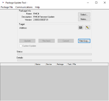
- Use the Address Book or the Pencil icon to connect to your processor and wait for it to connect
- Verify that the correct .puf and target device are selected
- Verify the information under "Package Info" matches what is expected for the desired firmware, and re-select the .puf using the "Select..." button if the information is incorrect
- Verify that the information under "Target" matches the device to be updated, and re-select the device using the Address Book or Pencil icon if it is incorrect
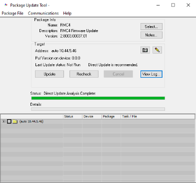
- Once you have verified all the information is correct and the Package Update Tool has run its check to see that the firmware is compatible with the device, click the "Update" button to begin the update
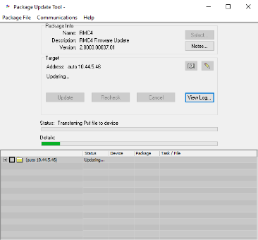
- The Package Update Tool will notify you of when it is safe to close, but it is recommended to stay connected if possible in order to verify that the firmware update has been completed successfully
Crestron Information Gathering Tool
The Crestron Information Gathering Tool is a valuable standalone piece of software that allows for easily recording current job-site status, such as online devices, their serial numbers, and their firmware versions. It is good practice to run this tool at the end of project start-up in order to document the project status.
In the event that a Crestron processor or ShowRunnerCLC™ installation behaves unexpectedly, Chief Integrations may ask for detailed logs from the Crestron Information Gathering Tool in order to analyze any issues and report them to Crestron if appropriate.
Steps
- Download and install the Crestron Information Gathering Tool
- The tool is available to download from the Resources tab on the SW-INFOTOOL Product Page
- Alternatively, the tool can be downloaded and installed through the Crestron MasterInstaller by running the MasterInstaller and selecting the "Information Gathering Tool" option
- Connect to the lighting network via Ethernet cable
- Ensure that the connecting computer's Ethernet settings are set to Static and the IPv4 address does not conflict with any devices already on the network
- Open Crestron Information Gathering Tool
- If gathering information for only one device:
- Input the IP address and login credentials for the device
- If no login credentials are necessary, leave username and password at default
- Select the desired output folder for the results
- Default location is "C:\Users\YourName\Documents\Crestron\InformationTool\Results"
- Select the appropriate Command List using the dropdown menu or use a custom command list by clicking "Select" and locating the command list file
- Ensure the PLOGs box is checked if collecting information for a processor (it should be checked by default)
- Press the Start button. It may take a couple of minutes for all the commands to finish running
- Input the IP address and login credentials for the device
- If gathering information for multiple devices:
- Click the "Batch Mode" button at the top of the window to open the Batch Mode window
- At the top of window, use the Devices > Autodiscover drop down menu to automatically add all discovered devices
- If not all devices are discovered (e.g. if there are devices that are only reachable through a router), then devices can be added from an Address Book
- If you do not already have an Address Book for the job, use Device Discovery Tool to perform a Local Search and generate an Address Book
- Then, use Device Discovery to perform a Remote Search and export the results to the same Address Book
- Alternatively, directly edit the Address Book .xadr file in a text editor to manually add any missing devices
- In the Batch Mode window, use the Devices > Import... drop down menu and locate the Address Book .xadr file to import the devices
- Press the "Model Name" column heading to sort devices by model
- For each model of device:
- Input the device credentials or leave the default values if authentication is not enabled for the device
- If the device is a ZUMNET-JBOX or ZUMNET-DIN, make sure the "PLOGs" box is unchecked and the "Connect Type" is set to CTP
- Select the appropriate Command List by clicking the "..." button in the Command List column, clicking "Select", and then locating the Command List file
- Right click anywhere on the device row and select "Copy to Same Model Devices" to apply these settings to all devices with the same model
- Be sure to update the credentials if different credentials were used for different, same-model devices
- Check the box in the "Enable" column to include it when gathering information
- Multiple devices can be enabled at once by ctrl+click, shift+click, or ctrl+A selecting multiple devices and then clicking "Enable Selected" from the right-click menu
- Once all desired devices are selected, press "Start Selected" in the lower right to begin collecting information on those devices
- Once the tool is finished running the commands, double check that no devices failed due to correctable issues (e.g. incorrect credentials) and re-run the tool for those devices if the issues are resolved
- If you have an Internet connection:
- Open the Uploader window by clicking the "Uploader" button at the top of the window
- Ensure all files are selected with a checkbox in the "Enable" column
- Check the "I agree to the Uploader Terms of Service" boxd
- Press "Send to Uploader"
- Share the URL in the "Your download link:" field with Chief Integrations or Crestron support for analysis
- If you do not have an internet connection:
- Navigate to the output folder in File Explorer
- Select all files and add to a .zip file using a tool such as 7-Zip
- Send this .zip file to Chief Integrations or Crestron support for analysis
Miscellaneous Tips
VPT COM Server
Whenever Toolbox is open, Toolbox also starts a separate process called the Crestron Toolbox VPT COM server. This process appears in the system tray with the following icon when active: 
Occasionally, something might go wrong with the VPT COM Server process which will prevent Toolbox from functioning correctly. To solve this problem, take the following steps:
- Close Crestron Toolbox
- Press CTRL+SHIFT+ESC to open Windows Task Manager
- Click the "More Details" button to see all processes
- Sort processes alphabetically and look for "VptCOMServer Module (32 bit)" under the "Background Processes" section
- If you do not see the VptCOMServer process in Task Manager and the icon is not in the system tray, then it is not running
- If the VptCOMServer process is still running after Toolbox has closed, select it in Task Manager and press End Process to stop it
- Once VptCOMServer is stopped, open Toolbox and see if your issues have been resolved
Alternatives to Specific Toolbox Tools
Sometimes it is necessary to connect to a Crestron device for troubleshooting using a computer that either does not or cannot have Toolbox installed on it. In these instances, third-party software can be used to replace some of the Tools in Toolbox in order to allow immediate troubleshooting of the lighting control system.
The Text Console tool can be substituted with PuTTY, a free and open-source Telnet and SSH client/terminal emulator. SecureCRT is another option with some more capability than PuTTY, but note that it is a paid software which requires a license to use. The File Management tool can be substituted with WinSCP, FileZilla, or CyberDuck. These are all free FTP/SFTP clients that do not require any license to use.
Note that any Text Console or File Management alternatives are only suitable when connecting to Crestron devices over TCP/IP (Ethernet). When connecting to a Crestron device using these third-party programs, use port 22. Connecting to Crestron devices over USB is only possible using Toolbox because these devices do not use a standard communications protocol for USB communications.