Zūm Wired Wiring Overview
Zūm Wired is a distributed lighting control system manufactured by Crestron that is set to replace the older Cresnet-based GLPP hardware. It uses industry standard 0-10V, phase dimming, and DALI protocols to allow for automated control of a building's lighting.
A Zūm Wired system consists of several devices that are joined on three distinct networks that each use the same cables and connectors as Ethernet. The three networks in a Zūm Wired system are:
- Ethernet
- Zūm Net
- Zūm Link
Additionally, traditional 4-wire Cresnet can be wired directly into a Zūm Link network; wiring details below.
Ethernet
Ethernet provides the backbone of the lighting network. Ethernet joins the Hub panels to each other, the processor, and (if the design calls for it) the building LAN. All Ethernet cabling should adhere to the Ethernet standards for Crestron systems.
Zūm Net
Zūm Net wiring should adhere to Ethernet cabling standards and use standard RJ-45 connectors. Zūm Net connects networked room-level controllers throughout the building to each other and to the lighting network. Each Zūm Net run will typically originate at a Hub or Processor panel and then connect to a number of ZUMNET-JBOX devices.
Typically, there is only one ZUMNET-JBOX per room. Zūm Net cable is shown in purple on Figure 1. It is very important to never connect a Zūm Link cable to a Zūm Net port as this may damage the Zūm net devices.
ZUMNET-JBOX devices are covered in more detail here.
Zūm Link
Zūm Link runs originate at a ZUMNET-JBOX and connect various Zūm Link devices within a room to the ZUMNET-JBOX for that room. Zūm Link cable is shown in orange on Figure 1. It is very important to never connect a Zūm Link cable to a Zūm Net port as this may damage the Zūm Net devices. Additionally, do not loop Zūm Link runs back to a Zūm Net device; each Zūm Link run should originate at an orange Zūm Link port on a Zūm Net device and end at the last Zūm Link device on the run.
Zūm Link to Cresnet
While most Zūm Link wiring will adhere to Ethernet cabling standards and utilize standard RJ-45 connectors, Zūm Link is not technically Ethernet. In some situations, it may be necessary to wire traditional Cresnet devices into a Zūm Link space.
In the future, Crestron will be producing a ZUMLINK-CNRJ45 adapter to allow for plug-and-play connections between Zūm Link RJ-45 connectors and 4-wire Cresnet devices. Until this product is available however, it is necessary to strip the Zūm Link wire and terminate it directly into a Cresnet phoenix connector or terminal block.
The pin-out to connect a Cresnet device to a Zūm Link network that has been terminated per the T568B Standard is as follows:
| RJ-45 Pin | Function | Cresnet Color | T568-B Color |
|---|---|---|---|
| 1 | 24V | Red | White / Orange |
| 2 | 24V | Orange | |
| 3 | GND | Black | White / Green |
| 4 | GND | Blue | |
| 5 | (N/C) | (N/C) | White / Blue |
| 6 | OVR | (N/C) | Green |
| 7 | Cresnet Y (Data +) | White | White / Brown |
| 8 | Cresnet Z (Data -) | Blue | Brown |
Figure 2 illustrates how a Zūm Link cable should be terminated at a Cresnet phoenix connector (recall that the standard left-to-right color code for Cresnet wiring is red-white-blue-black). Cresnet wiring is covered in more detail here.
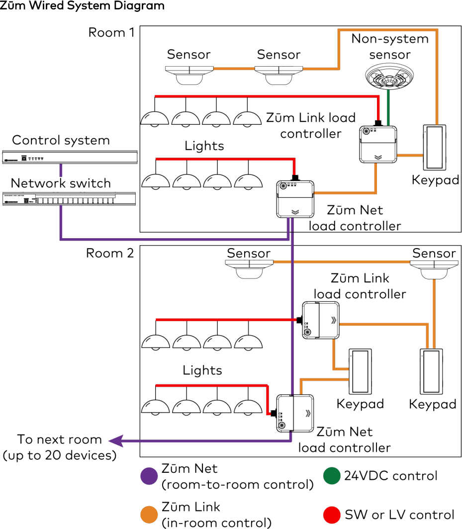
Figure 1: Overview of a typical Zūm Wired system
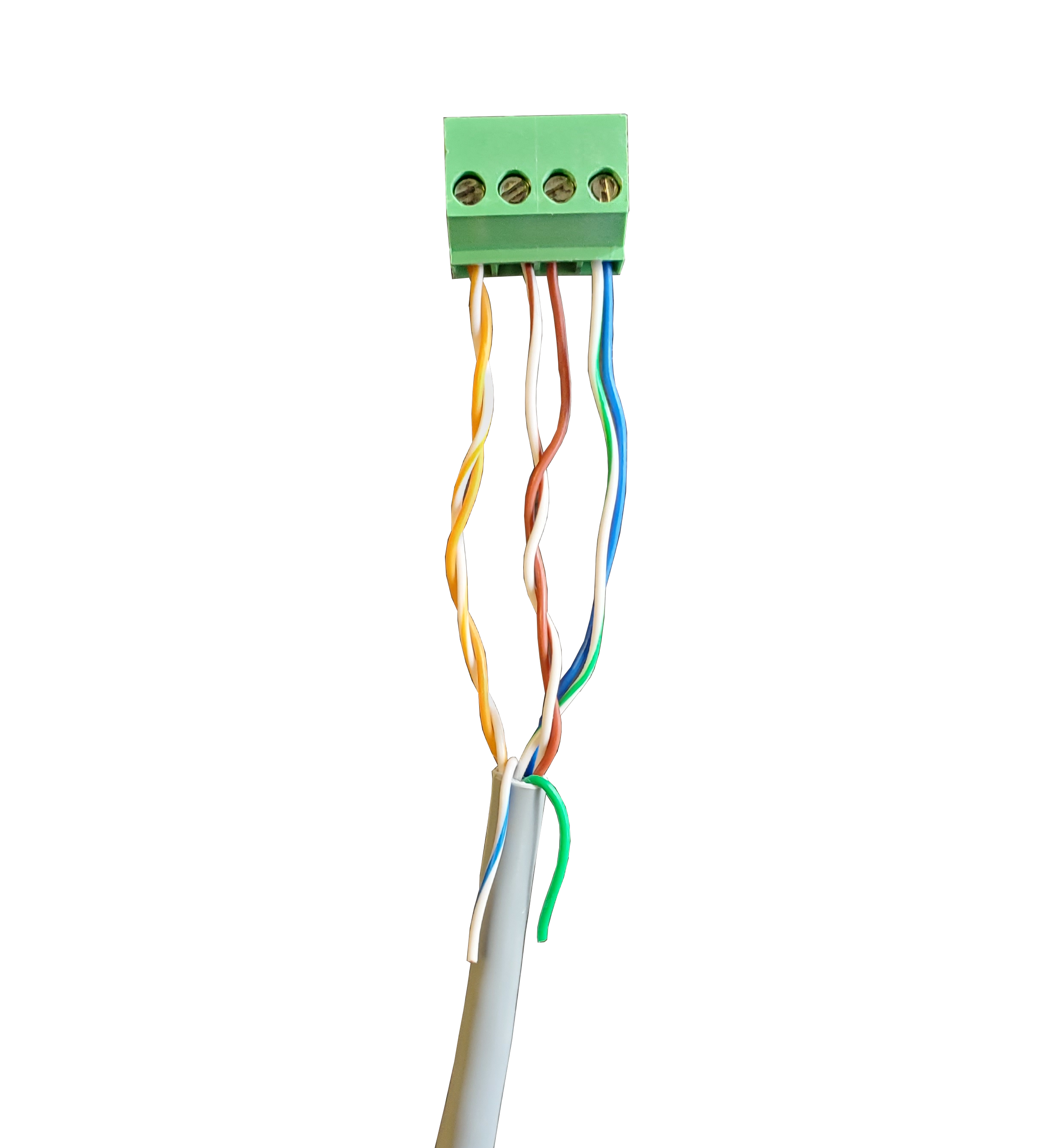
Figure 2: Zūm Link to Cresnet Wiring - white/blue and green wire left bare for illustration purposes only; during actual installation they should be capped and insulated.