Cresnet Wiring Overview
Communications between Crestron Cresnet devices occurs on the Cresnet bus. Cresnet is Crestron's proprietary 4-wire communications network that provides both 24V DC power and low-voltage, bidirectional communication adhering to to RS-485 standards.
Each job with Cresnet devices will have at least one Cresnet bus network. Every Cresnet bus network has a single host or primary device and one or more client or secondary devices (older materials may refer to hosts as masters and clients as slaves). Every Cresnet device on a Cresnet bus must be assigned a unique, one-byte hexadecimal Cresnet address. The range of available addresses is determined by the bus host:
| Host | Available Addresses | Start | End | Notes |
|---|---|---|---|---|
| 3-Series or 4-Series processors | 252 | 03 | FE | Chief Integrations has experienced significant communications slowdowns on systems with more than 100 devices, and recommends using DIN-CENCN-2(-POE) or additional processors to break up larger Cresnet bus networks |
DIN-CENCN-2 or | 25 per Net (50 total) | 03 | 1B | |
| ZUMNET-JBOX-16A-LV or ZUMNET-JBOX-DALI | 32 | 03 | 22 | ZUMNET-JBOX local controller counts as a device; only 31 additional Zūm Link or Cresnet devices may be connected Zūm Link and Cresnet can be intermingled; more details are available here |
Power considerations also play a role in determining the number of Cresnet devices which can be supported on a Cresnet bus, however we will not cover them here due to the wide array of variables which impact power calculations and determining whether there is sufficient power for a given device.
Cabling
Cresnet cabling provides the physical infrastructure for communication between Crestron Cresnet devices and consists of a 4-wire, 2-pair cable:
| Pair | Color | Purpose |
|---|---|---|
| 18 AWG pair | Red | 24 V DC Power |
| Black | Common | |
| 22 AWG shielded twisted pair | White | Data + |
| Blue | Data - |
Cable is available directly from Crestron with either plenum or non-plenum rated jackets.
While Cresnet can be run in either a daisy-chain or a star topology, Chief Integrations strongly recommends only running in a daisy-chain pattern in order to simplify troubleshooting and increase system reliability. Per Crestron, the maximum run length is 3000', but we strongly recommend keeping runs as short as possible in order to avoid issues with EMF interference and voltage drop.
Terminations
Cresnet runs originate at the host device in a Crestron Processor Panel (CPP) or Cresnet Hub (HUB) panel and connect to Cresnet devices that are located either in the field or in Lighting Control Panels (LCP). Most Cresnet terminations are done with Phoenix connectors which can be easily connected and disconnected to the device. Phoenix connectors have "flags" on the plug so that the connector can only be plugged into the device in one orientation. With the flags pointing up, the wire colors from left to right should be red-white-blue-black, corresponding to 24-Y-Z-G.
Devices that do not use Phoenix connectors will have red, white, blue, and black leads corresponding to the 24, Y, Z, and G wires of the Cresnet cable. All four of the individual Cresnet wires should be connected to the corresponding wire at the device using twist-on wire nuts except for at GLPPs, where only the white (Y), blue (Z), and black (G) wires should be connected. The red wire coming from the GLPP is reserved for providing power to non-system devices and should be capped off if there are no devices connected to the GLPP.
When stripping wires, do not strip more than is necessary and avoid leaving any exposed copper at the termination. While it is possible to fit two wires into each terminal of a Phoenix connector, it is a tight fit and many ECs find it easier to make a pigtail so that only one of each 24/Y/Z/G wire needs to be terminated at the connector. If making a pigtail for this purpose, be sure to use twist-on wire nuts (not lever-nuts) and avoid excessively long pigtails.
Drain Wire
It is important to pay attention to how the Cresnet drain wire (the bare wire that is part of the white/blue shielded twisted pair) is terminated, as failure to do so may result in communications issues that incur significant labor costs to correct. The drain wire provides a path to ground for electrical noise that may be caused by stray electromagnetic frequencies (EMF) acting on the Cresnet cabling.
The drain wire should be landed with the black ground wire at the CPP or HUB panel where the Cresnet run originates, spliced through at every device in the field, and capped off at the last device in the run. Think of the drain wire as an antenna that is only connected at one end (the CPP or HUB panel) and isolated everywhere else (at devices in the field). See Figure 1 for details.
Figure 2 includes detail on splicing the drain wire through in the field.
Crestron Wiring Notes
Crestron includes some general Cresnet wiring guidelines in their submittals. Many of these suggestions are covered above, but we have included them here for reference:
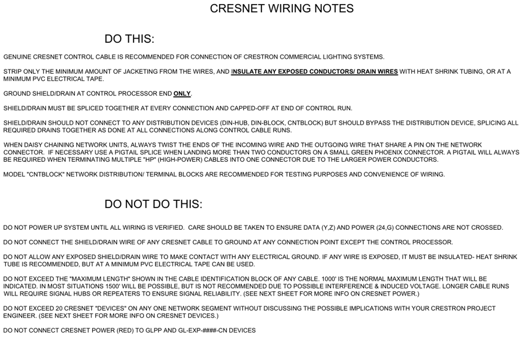
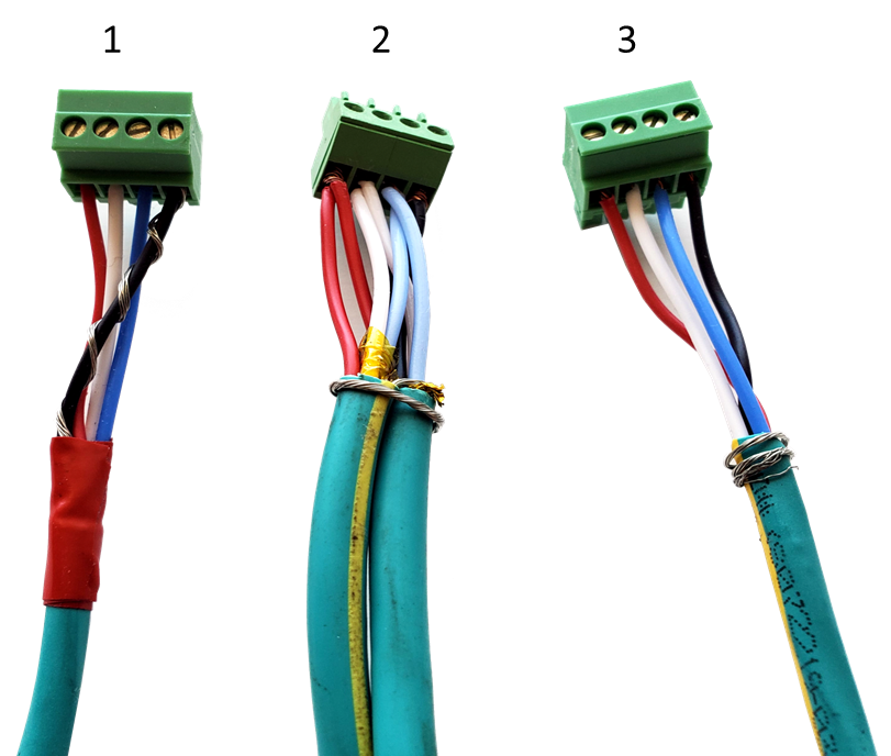
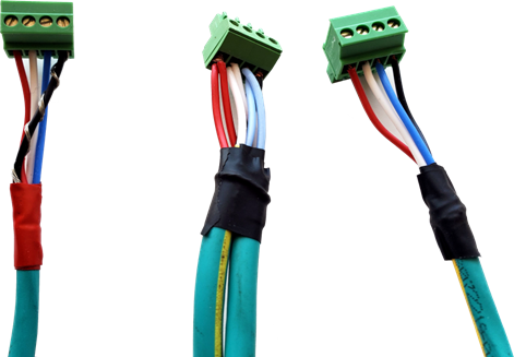
Figure 1: Cresnet terminations with Phoenix connectors. Drain wire left bare in top photo for illustration purposes only; actual installations should have the drain wire insulated as shown in the bottom photo.
Left: drain is terminated with ground (at run origin only), Right: drain wire is capped off (at end-of-line device only), Center: drain wire is spliced through (at all other devices)
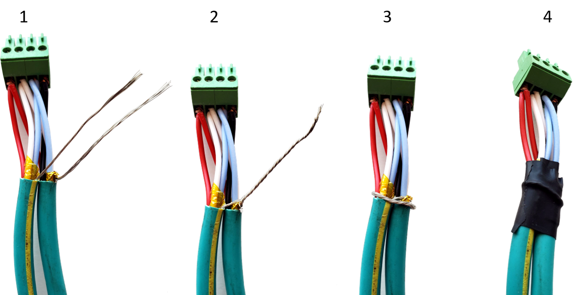
Figure 2: Demonstration of correctly splicing the Cresnet drain wire
1: drain wire is separated from other wires, 2: drain wire is twisted together, 3: drain wire is wrapped around jacketed portion of cable, 4: drain wire is insulated with PVC electrical tape