Ethernet Wiring Overview
Ethernet is used to connect various devices within a Crestron Lighting Control system to the lighting network as well as connecting the lighting network itself to a building network (building LAN). The term "lighting network" refers to the infrastructure that connects Ethernet-capable Crestron devices and allows for communication between them.
The lighting network will typically consist of Crestron panels with at least one Ethernet device and at least one Ethernet switch. The device(s) within a panel are connected to the Ethernet switch from the factory, but cabling must be provided to connect the Ethernet switches within separate panels to each other and to the building LAN (if such a connection is shown on the submittals). Additionally, some devices in the field (such as GLPAC lighting controllers or TSW touch screens) must be connected to the lighting network by running an Ethernet cable from their location in the field back to an Ethernet switch in one of the lighting panels.
Cabling
All cable should be Category 5e or greater (including Category 6 and Category 6a).
The maximum length of any single ethernet run is 100 meters (328 feet). Runs longer than this will require a powered ethernet switch (such as a CEN-SW-POE-5) to be installed midway through the run to enable proper communication.
Terminations
Cresnet Ethernet devices require the use of RJ-45 connectors. DO NOT use "EZ" or passthrough-style RJ-45 connectors. All RJ-45 connectors must be standard, closed-end type connectors to ensure correct functionality of the system.
While either T568A or T568B termination pin-out are acceptable as long as they are used consistently, it is recommended to use the T568B pin-out for all terminations. By keeping to one standard, it is easier to stay consistent and prevent errors where the two sides of a single cable are not terminated to the same standard.
See Figure 1 for the T568-B pin-out.
When making RJ-45 terminations, take care that the wires are in the correct order and pushed all the way to the end of the connector. A crimping tool with sharp blades that have not been dulled with use also helps in making good terminations.
Testing and Troubleshooting
Issues with Ethernet cabling typically will not be discovered until a lighting technician is on-site to commission the Crestron system. Commonly available cable verification testers (such as the Klein Scout) are useful in determining basic faults such as crossed, shorted, or broken wires, but the only way to definitively rule out Ethernet cable issues is with the use of a cable Qualification or Certification tester.
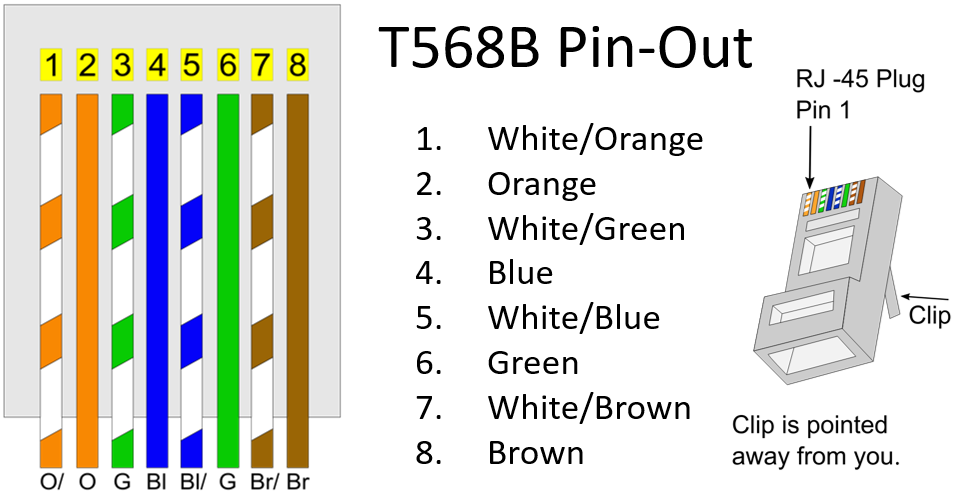
Figure 1: ANSI/TIA-568-B.2001 T568B Pin-Out