
Zūm Net Device Setup
Zūm Net devices are part of Crestron's latest Zūm Wired system, acting as the main lighting controller for a Zūm Wired room. In networked applications of Zūm Wired, they also act as bridges connecting the local Zūm Link devices in each room to the overall lighting network throughout the building. Since Zūm Link and Cresnet are interchangeable, and Zūm Net is an Ethernet protocol, this means that Zūm Net devices can be thought of as single-net DIN-CENCN-2s. As of fall 2026, there are only four Zūm Net devices in production: the ZUMNET-JBOX-16A-LV 0-10V, ZUMNET-JBOX-DALI, ZUMNET-DIN-16A-LV, and ZUMNET-DIN-DLI load controllers. Configuring these devices for use with ShowRunnerCLC™ is identical, so they will be referred to collectively as ZUMNET devices for the purposes of this article.
Much like DIN-CENCN-2s in ShowRunnerCLC™ installations, ZUMNET devices identify themselves to the processor via their IP-ID, so the specific IP address of any given ZUMNET device does not matter as long as it is in the same range as the processor and does not conflict with any other devices on the network. If hosted devices are moved between ZUMNET devices, or if the ZUMNET device needs to have a different IP-ID than it was initially assigned, the configuration will need to be updated (see below). Chief Integrations typically provides an SRTakeoff.xlsx spreadsheet which will list all the Zūm Net and Zūm Link devices and their associated IP-IDs. If no takeoff is provided, then the processor's IP table can be checked by running the ipt -t command from the processor after the configuration is loaded. ZUMNET devices will typically start with IP-IDs in the 30-5F range, but can potentially exceed this range.
Identification and IP Configuration
Configuring ZUMNET devices must be done over Ethernet, and is easiest to do once all ZUMNET devices have been installed, powered up, and connected to the lighting network. (It is not necessary for all Zūm Link devices to be installed in order to configure ZUMNET devices.)
Since there is no option to configure ZUMNET devices via USB, a DHCP server is required. There are three options for DHCP servers:
- Using a processor with a Control Subnet (only available on certain processors)
- Using the built-in ShowRunnerCLC™ DHCP Server (available on all processors running ShowRunnerCLC™ v3.009 or newer)
- Using third-party DHCP server software on your computer such as OpenDHCP
- Using a third-party router
Most devices (DIN-CENCN-2, TSW, ZUMNET devices) rely only on IP-ID to identify themselves to the processor, but some devices (such as GLPACs, DMX controllers, and other processors) have IP addresses that are explicitly defined in the configuration file. The DHCP server should be configured to assign IP addresses that are visible to the processor, but excluded from assigning these explicitly defined IP addresses if possible.
Configuring ZUMNET devices can be broken up into two separate processes:
- Identifying which DHCP assigned IP address corresponds to each ZUMNET device
- Connecting to each ZUMNET device and assigning a permanent static IP address and IP-ID
Identifying ZUMNET Devices
Once all ZUMNET devices have been assigned temporary IP addresses from the DHCP server, they must each be identified so that the correct IP-ID can be assigned. The goal is to associate each assigned IP address with the room that each ZUMNET device is meant to control. Then we can connect to each ZUMNET device and set static IP addresses and update the IP table with the correct IP-ID.
There are three primary ways of identifying ZUMNET devices:
- Identifying by hostname
- Identifying by serial number or MAC address
- Identifying through Device Tree View
- Identifying by load flashing
Each of these methods involves generating a Device Summary using the Device Discovery Tool in Toolbox. The Device Summary is a file which lists all devices that are discoverable on the network along with useful information such as their hostname, IP address, and MAC address.
To generate a Device Summary in Toolbox:
- Connect to the lighting network and open Device Discovery Tool in Toolbox
- The Device Discovery tool will automatically report how many Ethernet devices have been discovered
- Verify that the expected number of Ethernet devices have been discovered, including any TSWs, GLPACs, DIN-CENCN-2s, etc.
- Note that only Crestron devices will appear in Device Discovery; non-Crestron devices (such as Pharos or Enttec DMX controllers) will not appear in Device Discovery Tool
- If no devices are discovered, verify that your computer is connected to the network and your IP address is compatible with the network
- If some devices are missing, there may be an issue with your DHCP server settings or the network wiring
- Click the "Export..." button below the list of discovered devices
- If this button says "Address Book", then Toolbox needs to be updated
- Click the Write Device Summary button and save the Device Summary to your computer
- Though saved as a text file, the Device Summary is actually a table of comma separated values
- Renaming DeviceSummary.txt to DeviceSummary.csv will allow it to be opened and manipulated in common spreadsheet software such as Microsoft Excel or LibreOffice Calc
See the Export to Device Summary section of the Toolbox Basics page for more detail.
Once the Device Summary has been generated, proceed to identifying each ZUMNET device using the hostname, SN/MAC, or Device Tree View methods described below.
Identifying by Hostname
The Crestron Zūm App is used to configure the internal logic of Zūm Wired rooms. This internal logic determines the room behavior when ZUMNET devices are used in standalone applications or if communication to the processor is lost. Even on ShowRunnerCLC™ jobs with a central program running the lighting controls, it is best practice to configure the internal logic to match as closely as possible the ShowRunnerCLC™ logic in order to minimize disruption to end-users in the event of a processor or network failure.
In addition to configuring default room logic, the Crestron Zūm App can be used to change the hostname of the ZUMNET device for each room. By default, the hostname for a ZUMNET device is the model followed by the last six digits of the MAC address, e.g. "ZUMNET-JBOX-16A-LV-F2DA94". If you or the electrical contractor already intend to configure the internal logic each ZUMNET device, it would be a good idea to also change the hostname to something more identifiable.
To change the hostname using the Crestron Zūm App:
- Connect to the ZUMNET device in the App
- Tap "Room Settings"
- Tap "Network"
- Tap the Hostname field and edit the Hostname
- Scroll to the bottom of the page and tap "Save settings"
- Tap "OK" to apply the changes and reboot the ZUMNET device
- Note that rebooting the devicewill cause the lights to briefly cut out
If all hostnames have been set, then it becomes very easy to know which DHCP assigned IP address is associated with each room using the Device Summary. Generate a Device Summary with the new hostnames and proceed to IP configuration.
Full instructions on configuring Zūm Wired using the Crestron Zūm App, can be found here.
Identifying by Serial Number or MAC Address
Both the serial number and MAC address are printed onto each ZUMNET device. Just like with Cresnet jobs, it is good practice for the electrical contractor to record serial numbers as they install devices. It is also good to collect the MAC addresses, but it is not necessary since Device Summary will have both the serial number and MAC address.
If the electrical contractor has provided a list of which serial numbers/MAC addresses belong to each installed ZUMNET device, then generate a Device Summary and proceed to IP configuration.
Identifying Through Network Device Tree View or Text Console
If the electrical contractor has not provided a list of which serial numbers/MAC addresses belong to each installed ZUMNET device and nobody intends to rename each ZUMNET device using the Crestron Zūm App, then the only way to identify which ZUMNET device is installed where is to use the Device Tree View tool in Toolbox. This is by far the slowest and most disruptive way to identify devices, so it is only recommended as a last resort.
Putting a ZUMNET device into identify mode will make it continuously produce an alarm-clock sound and flash any connected loads (newer firmware/models will produce a regular beep rather than an alarm-clock sound). Additionally, putting a device into identify mode will stop any programs running on a processor, and taking a device out of identify mode will restart the program. This starting/stopping of the program can be time consuming when a large number of devices are being identified, so it may be a good idea to suspend the program using the stopprog -p:01 command on the processor prior to identifying devices. Once all the devices are identified, run the progreset command to resume the program.
Connected ZUMLINK devices (including keypads, occupancy sensors, etc.) can also be put into identification mode
- Generate a Device Summary and note the IP addresses for all installed ZUMNET devices
- Connect to the first ZUMNET device using Network Device Tree View or Text Console
- From Device Tree View
- Locate the "ZUMNET-*-LOCAL" device in the list of connected devices
- The model will vary between 0-10V and DALI devices
- The ID should be "03" regardless of model
- Right click the device and press "Identify This Device..." from the context menu
- Locate the "ZUMNET-*-LOCAL" device in the list of connected devices
- From Text Console
- Run the command ppndiscover to see a list of connected devices and their 8-digit, hexadecimal TSID
- Run the command lightbyppn 1 [TSID] to put the device into identification mode
- Run the command stoplightbyppn 1 [TSID] to take a device out of identification mode
- Running either of these commands without parameters or with "all" as the TSID will identify or stop identification on all connected devices
- From Device Tree View
- The device will blink any controlled fixtures and make an alarm sound
- Walk around the jobsite until the room/controlled fixtures are located
- Edit the Device Summary or SRTakeoff.xlsx so that you remember which device is which
- Once identified, take the device out of identification mode through the Toolbox GUI or using the stoplightbyppn Text Console command
- Repeat for each ZUMNET device until all of the ZUMNET devices have been identified
Once you have determined and recorded which ZUMNET device is which, you may proceed to IP configuration.
Identifying by Load Flashing
This method is the same as identifying through Device Tree View, except instead of putting the device into identification mode, you either manually toggle the load using the "TEST" button on the device or you temporarily configure it as a device in the configuration and control it through ShowRunnerCLC™. Once identified, you reconfigure it with the correct IP-ID and CID.
Assigning Permanent Static IP Addresses and IP-IDs
Once you have identified which IP address has been assigned to each ZUMNET device, you can begin configuring them with permanent static IP addresses and the correct IP-ID.
Note that static IP addresses are only required on jobs where there is no permanent DHCP server. Manual IP-ID assignment is not required for jobs intended to be used with Zūm Auto Discovery, though it may still be recommended in order to keep track and document which IP-ID is associated with each area (Auto Discovery will auto-assign IP-IDs to ZUMNET devices without IP-IDs, but if a ZUMNET device already has an IP table entry it will be imported to the configuration with that pre-existing IP-ID).
- Open Text Console in Toolbox and connect to the first ZUMNET device
- Run the following commands to configure the ZUMNET devices IP settings (example is for a 10.0.0.0/24 subnet, with a permanent IP address of 10.0.0.80, an IP-ID of 30, a processor IP address of 10.0.0.10, and a hostname of ZNET-JBOX-RM-201; the hostname can be skipped if it has already been configured from the Crestron Zūm App)
- Set IP address: ipa 0 10.0.0.80
- Set IP subnet mask: ipm 0 255.255.255.0
- Set default gateway: defr 0 10.0.0.1
- Update IP table: addm 30 10.0.0.10
- Set hostname: host ZNET-JBOX-RM-201
- Disable DHCP: dhcp off
- Reboot the ZUMNET device: reboot
- Note that rebooting the device will cause the lights to briefly cut out
- Repeat for all ZUMNET devices on the job
Zūm Net Specific Configuration
Zūm Net devices have a two additional settings not present for other devices: Primary/Secondary mode and Zūm/Cresnet mode. ZUMNET device DALI have a third setting for Group/Legacy DALI mode, and all ZUMNET device-* that are in CNET mode can optionally be configured to automatically switch back and forth between CNET and App mode depending on whether the control processor is reachable.
Updating Firmware
It is best practice to upgrade all Zūm Wired devices to the latest version, or at the very least update all devices to the same firmware version across the job. The recommended process for updating Zūm Wired firmware is:
- Ensure that the ZUMNET device for the room is in Primary / Zūm Mode (see below) so that it will re-address all connected Zūm Link devices
- Connect to the ZUMNET device in Network Device Tree View and verify that all expected Zūm Link devices are online and that there are no conflicting/duplicate IDs
- We have run into issues where devices will not always be uniquely addressed, typically as a result of cabling termination issues (incorrect pin-out or use of "EZ RJ45" passthrough connectors)
- Occasionally, ZUMLINK-KP will be stuck at ID 03 after the ZUMNET device has been put into Primary/App Mode - in these cases, briefly disconnecting the keypad, reconnecting it, and waiting a few minutes will allow the keypad's address to be changed
- Use the Zūm Wired .puf file or the Firmware Updating Script tool built into ShowRunner™ to update all the ZUMNET devices
- Note that as part of the update process, the ZUMNET device will reboot, which will cycle the connected load and briefly interrupt Ethernet connection to any downstream ZUMNET devices or other Ethernet devices, which in rare instances will cause the firmware update to fail
- Verify that all the ZUMNET devices have successfully updated by using the Device Discovery Tool device export and checking the reported firmware version
- If any ZUMNET devices failed to update, try to update it again in case the update failure was caused by an upstream device rebooting
- If a ZUMNET device fails to update more than twice in a row, further investigation is required:
- ZUMNET devices will update their firmware only after all connected Zūm Link devices have been successfully updated
- If any connected Zūm Link devices have conflicting or duplicate IDs, the update will fail
- Zūm Link cabling issues may also cause firmware updates to fail
- An unstable network (Ethernet) connection to the ZUMNET device may also cause the update to fail
- ZUMNET devices will update their firmware only after all connected Zūm Link devices have been successfully updated
Alternatively, rooms can be updated through the Crestron Zūm App as of firmware v1.03.54, however only one room can be upgraded at a time and your mobile device will become occupied for the duration of the firmware upgrade (15-45 minutes depending on firmware version and quantity of Zūm Wired devices in the room)
Primary/Secondary Mode
ZUMNET devices can be in either "Primary" or "Secondary" mode. In most situations, "Primary" is the desired mode of operations, as "Secondary" mode effectively turns a ZUMNET device into a ZUMLINK device and prevents it from discovering devices on the Zūm Link bus or performing any logic. There are two scenarios in which a ZUMNET device should be configured in "Secondary" mode:
- It is connected to another ZUMNET device via the Zūm Link bus
- It is being used as a Cresnet device, connected to a processor or DIN-CENCN-2 using a Cresnet/Zūm Link adapter
ZUMNET devices with firmware 1.006.00012 or newer will ship from the factory in "Primary" mode, but will go to "Secondary" mode if a hardware reset is performed. ZUMNET devices with older firmware will ship in "Secondary" mode. The commands to view or change the Primary/Secondary mode are:
- View current mode:
- Current FW: zwps or zwmode
- Old FW: zwms
- Make "Primary":
- Current FW: zwps primary
- Old FW: zwms master
- Make "Secondary":
- Current FW: zwps secondary
- Old FW: zwms slave
A reboot is required if the mode is changed.
ZUM/CNET Mode
Zūm Mode (also known as App Mode) is the default setting for ZUMNET devices shipping on newer firmware, and allows them to be configured from the Crestron Zūm App as long as a ZUMLINK-KP is connected to the device. If a ZUMNET device is put into Cresnet mode, it will no longer be able to be configured using the Crestron Zūm App and all internal logic will be disabled.
Generally, ZUMNET devices do not need to be in Cresnet mode to work with ShowRunnerCLC™ except in specific cases:
- ZUMNET-JBOX-DALI controllers are being used in legacy mode
- Site-specific security requirements do not allow for wireless connectivity to the lighting controls
- Certain ShowRunnerCLC™ features are required (such as changing the dimming response curve)
- On older versions of firmware, Cresnet mode was required if non-Zūm Link devices were connected to the ZUMNET device (e.g. a GL-EXP-DIMU-CN phase dimmer or C2N-CBD-P Cameo keypads)
- This is no longer the case on recent firmware, and ZUMNET devices with Cresnet hardware connected to them can be left in Zūm/App mode, though the Cresnet hardware will not be able to function without the control processor
When a ZUMNET device is in Zūm Mode and configured to communicate with a processor running ShowRunnerCLC™ software, it is operating in a kind of "App Plus" mode, where any actions that are defined in ShowRunnerCLC™ are performed "on top of" the actions defined in the App:
- A keypad with actions defined in the Zūm App will perform actions defined in ShowRunnerCLC™ in addition to those App-defined actions while the ZUMNET device is in Zūm Mode
- This is useful when trying to add functionality to a keypad, such as allowing the keypad to control devices not available in the Zūm App (e.g. shades, loads that are controlled by other ZUMNET devices or Cresnet load controllers, etc.), but can cause confusion in other situations where there are conflicts between the App-defined actions and the ShowRunnerCLC™-defined actions (e.g. if a rocker keypad with the default All On and All Off actions defined in the App is programmed in ShowRunnerCLC™ to act as a single load toggle, it will not work correctly)
- A ZUMLINK-KP that is disabled from ShowRunnerCLC™ (i.e. by using the Keypad Disable function) will not perform any actions
- A ZUMLINK-KP that has null actions defined in the Zūm App will only perform those actions that are defined in ShowRunnerCLC™
- If occupancy sensor load assignments in the App do not match ShowRunnerCLC™, then odd behavior may result
The commands to view or change the Zūm/Cresnet mode are:
- View current mode: zwmode
- Make Zūm/App mode (causes automatic reboot): zwmode zum
- Make Cresnet mode: zwmode cnet
Manual reboot required when changing to CNET mode; changing to ZUM mode will automatically reboot the device.
DALI Group/Legacy Mode
ZUMNET-JBOX-DALI that are operating in App mode should be kept in "Groups" DALI mode, and DALI loads must be configured through the Zūm App. ZUMNET-JBOX-DALI that are operating in CNET mode with ShowRunner™ must be changed to "Legacy" DALI mode, and the DALI ballasts must be addressed and grouped using the Crestron Toolbox DALI Commissioning 2.0 Tool. It is not possible to take ZUMNET-DIN-DLI out of App or Groups mode.
If a ZUMNET-JBOX-DALI in App/Groups mode or a ZUMNET-DIN-DLI fails, the device must be reconfigured from the Crestron Zum App in addition to the regular configuration detailed above. A ZUMNET-JBOX-DALI in CNET/Legacy mode requires no additional DALI ballast reconfiguration if it is replaced; it can simply be swapped out and reconfigured as though it were a 0-10V or switching controller.
To change modes, run the appropriate dalisetmode command and then run reboot command immediately:
- Set Legacy mode: dalisetmode 1 1
- You must run zwmode cnet first, but rebooting between the commands is not necessary
- Set Groups mode: dalisetmode 1 2
- This command should not need to be run: zwmode zum automatically sets it and any ZUMNET-JBOX-DALI in CNET mode must also be in legacy mode
Zūm Mode Autoswitch
Zūm Mode Autoswitch is a feature introduced by Crestron in November of 2022 with .puf firmware v1.04.05 (device firmware 1.004.00005). This feature is intended to address concerns that arose from projects using custom programs with ZUMNET-* devices in CNET Mode. Previously, if a device in CNET Mode lost connection to the processor, then it would be impossible to maintain any sort of control over the lighting. With Zūm Mode Autoswitch enabled, a ZUMNET device running in CNET Mode will automatically switch to App Mode and process local logic in the event that it loses connection to the processor.
Note that on 0-10V and switched devices, the connected loads will flash once when rebooting. On ZUMNET-DALI-JBOX models, the JBOX will reboot once when switching to App mode and twice when switching back to CNET mode (once to switch to CNET, and a second time to switch to Legacy DALI mode)
Enable Zūm Mode Autoswitch using the command: autoswitch on
Rebooting after changing Autoswitch modes is not officially required, but is still recommended.
Any configuration changes made through the Zūm App should be made while the control processor is disconnected: the easiest ways to accomplish this are to either disconnect the Cat5e/Cat6 cable at the processor or use Text Console commands (stopprog -p:01)to temporarily suspend the custom program on the processor.
Changing IP-IDs
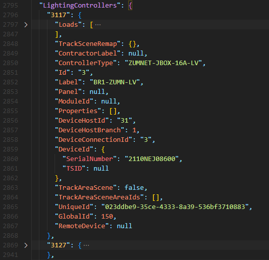
If ZUMNET devices must be assigned different IP-IDs than those indicated in the SRTakeoff.xlsx, or if Zūm Link devices are moved between ZUMNET devices, then the configuration file must be updated. Every Zūm Link device in the configuration has a "DeviceHostId" associated with it, which corresponds to the IP-ID of the ZUMNET device hosting it.
If a Zūm Link device is moved from one ZUMNET device to another, then this "DeviceHostId" must be updated with the IP-ID of the new device. Its "DeviceConnectionId" may also need to be updated to avoid overlapping with any devices already connected to the new ZUMNET device.
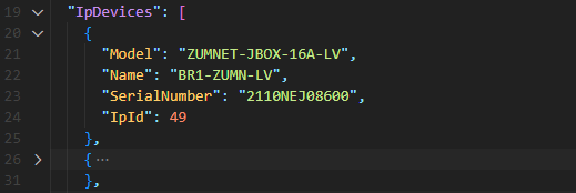
If a ZUMNET-JBOX is assigned a different IP-ID, then it's own "DeviceHostId" as well as the "DeviceHostId" for all hosted Zūm Link devices must be changed to the new IP-ID. In addition to changing these "DeviceHostId", the "IpId" for the associated entry in "IpDevices" must be updated. "IpDevices" are located towards the beginning of the configuration file. Note that while the "DeviceHostId" is in hexadecimal, the "IpId" is a decimal integer. This means that a ZUMNET-JBOX with "DeviceHostId": "31" would be associated with an entry in "IpDevices" with "IpId": 49
Below are two snippets from a configuration file comparing a ZUMNET-JBOX-16A-LV lighting controller and it's associated entry in "IpDevices":
NET, LINK, and TEST Indicator Lights for Zūm Wired JBOX/DIN
There are indicator lights on both ZUMNET and ZUMLINK devices which can give some clues as to the current state of the device. Both ZUMNET and ZUMLINK devices have LINK and TEST lights, while ZUMNET device have an additional NET light. The table below details all of the known possible states based on devices running firmware v4.01.11 (it is possible, though unlikely, that behavior may be different on other firmware versions)
| Light | State | Explanation | Notes / Potential Causes |
|---|---|---|---|
| TEST | Solid green | Output is on (relay is closed / any DALI load is on) | This does not mean the output is at 100%; a 1% dimmed output will still have a green test light |
| Off | Output is off (relay is open / all DALI loads are off) | ||
| Blinking red | Device is in override mode (OVR and GND ports on terminal block are shorted) | Long red blink with brief off period | |
| LINK | Steady green blinking | Device is the primary controller for the room Active communication over the ZUMLINK bus | Only one controller per ZUMLINK network should have a blinking green TEST light; multiple primary controllers on one ZUMLINK bus will cause issues Red flashing should be sporadic and only occur while there is active communication over the ZUMLINK bus (e.g. when a keypad is pressed, there is a firmware update in progress, etc.) |
| Erratic red flashing | |||
| Solid green | Device has communication with the primary controller | Controllers in secondary mode and non-controller (keypad, occupancy, etc.) devices only; primary controller should always have a steady green blinking | |
| Off | Device does not have communication with the primary controller | ||
| Steady red blinking | Device has an error: contact Crestron support (will likely need replacement) | Steady blinking, about once per second | |
| NET | Solid green | The device is communicating with the processor (IP Table shows online) | |
| Off | The device's IP table entry has not been online since the last time the ZUMNET has been rebooted or powered on | The device's IP table has not been set or has been set incorrectly (wrong IP-ID or target address) | |
| Solid Red | A previously online IP table entry is no longer online | Same potential causes as "Off" If the ZUMNET is power cycled or rebooted, the NET light will turn off | |
| Steady red blinking | Device has an error: contact Crestron support (will likely need replacement) | Steady blinking, about once per second |