Pharos Configuration
ShowRunner™ can control DMX fixtures through several different methods, including Pharos DMX controllers. The most common Pharos controllers sold through Crestron are the Pharos LPC-1 (DIN-DMX-1UNIVERSE) and the Pharos LPC-2 (DIN-DMX-2UNIVERSE). These LPC controllers appear physically identical, but the LPC-1 shares a single universe across both DMX outputs while the LPC-2 has a separate universe for each output. ShowRunner™ uses the Pharos Controller API to send commands over Ethernet to the Pharos Controller, which then sends DMX commands to the fixtures.
This article covers the basics of Pharos Designer 2 for the purposes of integrating with ShowRunnerCLC™ installations. Further information can be found from the official Pharos Designer 2 documentation.
Pharos Projects
ShowRunner™ integrates with Pharos LPC DMX controllers using the Pharos API. The ShowRunner™ configuration and the Pharos project loaded to the Pharos LPC need to be in coordination with each other in order for ShowRunner™ to control the DMX loads as expected. It is therefore sometimes necessary to either create or edit a Pharos project in order to determine how the DMX loads need to be defined in the ShowRunner™ configuration.
Creating a New Pharos Project for ShowRunner™
Pharos projects are created using the free Pharos Designer 2 software from Pharos Controls. When creating a project for use with ShowRunner™, ensure that API version 5.0 is selected for the project. Individual loads control from ShowRunner™ is achieved with group-level commands using the Pharos Controller API, so each Fixture Group defined in the Pharos Project should correspond to a single load in ShowRunner™. In addition to group-level commands, ShowRunner™ also supports mapping ShowRunner™ Scenes to Pharos Timelines.
When creating a Pharos project for a ShowRunner™ installation, there are several things to consider:
- Individual loads defined in ShowRunner™ send commands to individual Fixture Groups in Pharos
- Scenes in ShowRunner™ can be mapped in order to trigger Timelines in Pharos
- The Pharos API limits group-level commands to intensity, intensity/RGB, and intensity/CCT
- Other fixture profiles are still supported: the Pharos controller will do any necessary processing to adapt the commands to the fixtures
- For example, if Pharos receives an RGB command for a group containing RGB, HSI, and HSIC fixtures, it will mix the DMX channels to achieve a consistent color output across all the different fixture types
- Certain manufacturer-specific fixture Profiles exist in order to help the Pharos controller achieve a consistent output across multiple different fixture types
- Other fixture profiles are still supported: the Pharos controller will do any necessary processing to adapt the commands to the fixtures
- To control the RGB and white channels of an RGBW fixture separately in ShowRunner™, it is necessary to define separate RGB and White fixtures in the Pharos project
- Add both a generic RGB fixture and a generic White fixture to the layout
- Assign each fixture to a different group
- Patch the RGB fixture
- Patch the White fixture immediately following the RGB fixture (e.g., if the RGB is at address 1, patch the White fixture to address 4)
- Individual Fixtures can belong to multiple Fixture Groups, allowing ShowRunner™ to send different types of command (e.g. RGB vs CCT) to the same fixture
- Useful for certain situations, such as HSIC fixtures that need to be controlled as color-changing (RGB) in some situations but dynamic white (intensity/CCT) in others
- In this scenario, one group would be defined in ShowRunner™ as an RGB load and one group would be defined as a Dynamic White load
The basic steps for creating a Pharos Project for use with ShowRunner™ are as follows:
- Open the Pharos Designer 2 software
- Note that the version of Designer 2 lines up with the version of the Pharos controller firmware, and that any project that is created or edited in one version of Designer 2 will not necessarily be able to be loaded to a controller that is running older firmware without first updating the firmware
- In the top-right, click "New Project" and select the type of Pharos controller that will be the primary controller
- Crestron SKUs DIN-DMX-1UNIVERSE and DIN-DMX-2UNIVERSE both correspond to "LPC" in Pharos
- Navigate to the "Project" page by clicking the Pharos logo on the left
- Under the "Controller API" heading, verify that API Version 5.0 is selected
- Navigate to the "Network" page by clicking the network icon on the left
- Select "Controller 1" and verify that the number of universes in the "Properties" menu matches the controller that was ordered for the job
- If required, click the "New Controller..." button to add additional Pharos controllers
- Navigate to the "Layout" page by clicking the pencil and ruler icon on the left
- Overview of completed layout:
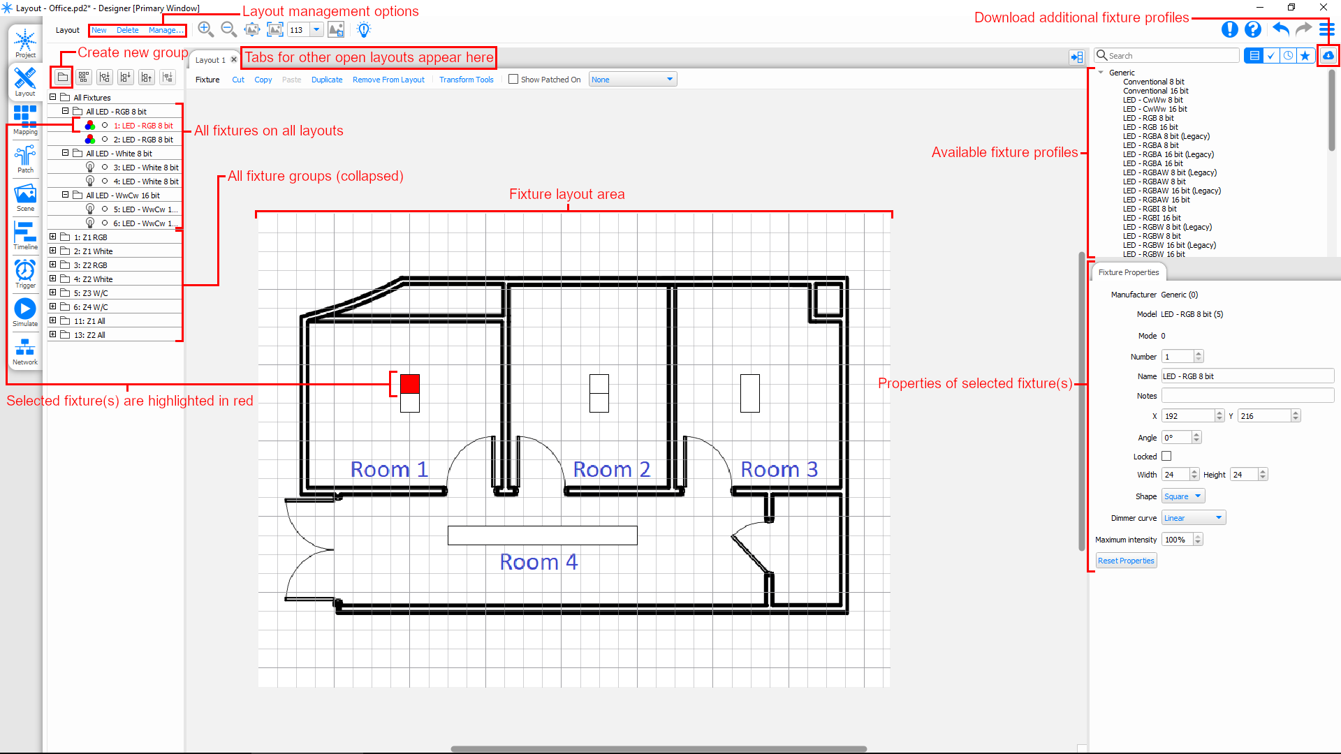
- At the top left, click "Manage..." to edit the layout name and dimensions, modify grid settings, and upload a background image if desired
- Locate the desired fixture in the Fixture Profile List on the right side of the Layout page
- Most fixtures can be controlled correctly using the generic single-channel, RGB, warm/cool, intensity/CCT, HSIC, etc. profiles
- Additional generic and manufacturer-specific profiles can be downloaded by clicking the cloud icon on the right, above the fixture profile list
- Add fixtures to the layout by dragging them from the Fixture Profile List
- Every fixture that is added to the layout represents a unique set of DMX addresses
- The fixture number is different than the fixture address, and is automatically incremented by Pharos Designer 2
- Fixture properties such as name, shape, and size can be edited using the menu on the right
- Right-clicking a fixture on the layout will allow you to either "Duplicate" or create a "New Instance" of a fixture
- Duplicating a fixture creates a new fixture with the same profile and properties but that will occupy different DMX addresses
- Creating a New Instance will create a new representation of the fixture without actually creating a new fixture; this allows you to have multiple fixtures represented on the layout that share the same DMX address
- Create Fixture Groups by clicking the folder icon above the Fixture List on the left or by right clicking an empty area in the Fixture List
- Fixture Groups will correspond to individual loads in ShowRunner™
- When a new Fixture Group is created, all currently selected fixtures are automatically added to the group
- Clicking a fixture on the layout or in the fixture list will select just that fixture
- Ctrl-clicking a fixture will add or remove it from the current selection
- Ctrl-dragging on the layout will add multiple fixtures to the current selection
- Shift-dragging on the layout will select just the highlighted fixtures
- Fixtures can be removed from a group by right clicking them under the group in the Fixture List
- Fixtures can be added to an existing group by selecting and then dragging them to a group in the Fixture List
- Note: dragging a fixture from one group into another will not remove it from the first group, only add it to the second group. Be careful not to accidentally assign fixtures to more groups than intended.
- Once all fixtures have been laid out and grouped, navigate to the "Patch" page
- Overview of a completed patch:
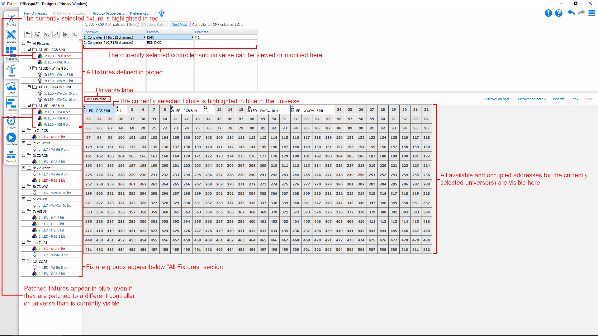
- All fixtures and fixture groups in the project will appear in a hierarchical tree view on the left
- All fixtures are present, regardless of grouping or which layout they appear on
- Fixtures will appear multiple times: once in the "All Fixtures" section, and then again in any groups that they are assigned to
- Patched fixtures have blue text, even if they are not patched to the currently visible universe
- Unpatched fixtures have black text
- The currently selected fixture has red text regardless of whether it is patched or not
- Current patching is viewed on the screen to the right
- By default, all universes on all controllers are shown
- Displayed universes can be narrowed down by selecting controllers and outputs from the list of controllers
- The currently selected fixture is highlighted in red in the fixture list and in blue if it is patched to the currently visible universe
- All fixtures are present, regardless of grouping or which layout they appear on
- Patch fixtures by dragging them from the fixture list onto the DMX universe
- If there are multiple controllers on the job, make sure that the correct controller and universe is selected and displayed on the right
- For controllers with multiple universes, ensure that the fixtures are patched to the correct universe
- Fixtures can be patched to multiple addresses, but it is not possible to patch multiple fixtures to the same address
- Fixtures can be unpatched by right clicking them in the universe
- If desired, navigate to the "Timeline" page and create timelines
Discovering Pharos LPC controllers and uploading a project are covered in detail in the Pharos Configuration section below.
Editing an Existing Pharos Project
If modifications need to be made to a Pharos Project that is already working with ShowRunner™, there are some things that should be taken into consideration in order to avoid breaking the existing programming:
- The version of Pharos Designer 2 is tied to the version of the Pharos controller firmware. Editing an existing project with a newer version of Designer 2 than the project was last saved in may result in the newly edited project no longer being able to be loaded to the controller without updating the controller firmware.
- To maintain full backwards compatibility with an existing installation, verify the controller's current firmware version and then download the corresponding version of Designer 2 from Pharos Controls' website
- ShowRunner™ does not pay attention to how Pharos DMX fixtures are addressed, only how they are grouped. Re-patching fixtures (changing their address) is covered in the Fixture Addressing and Identification section below.
- ShowRunner™ provides direct control of Pharos fixture groups by their group ID. Avoid changing Pharos fixture groups or group numbers unless you are aware of how they are mapped in ShowRunner™
- Adding newly patched/addressed fixtures to existing groups that are mapped in ShowRunner™ will allow those fixtures to be controlled without adding them to the ShowRunner™ configuration
- Removing fixtures from existing groups that are mapped in ShowRunner™ will prevent those fixtures from being controlled unless they are also in another group that is mapped to a ShowRunner™ load
- Renumbering a group that is mapped to a load in ShowRunner™ will prevent ShowRunner™ from controlling that group, unless the new number is also mapped in ShowRunner™
- If a new group is created that has the same group ID as a group that is already mapped in ShowRunner™, then ShowRunner™ will control that new group using the old load unless the ShowRunner™ configuration is updated
- ShowRunner™ maps Scenes to Pharos Timelines by their timeline ID
- Avoid changing Pharos timeline IDs unless you are aware of how they are mapped in ShowRunner™
- If a new Timeline is added that replaces the ID of an old Timeline, then the scene mapping in ShowRunner™ needs to be updated to prevent the old ShowRunner™ Scene from triggering the new Timeline
- If an existing Timeline is deleted, it should be unmapped in ShowRunner™ to prevent errors when the mapped ShowRunner™ Scene is recalled
Pharos Configuration
ShowRunner™ must be able to communicate with the Pharos controller via Ethernet in order for control to work. Pharos controllers ship in DHCP mode by default, but they will sometimes fail to get an address if the controller is powered up before the DHCP server is running. If this happens, or if there is no DHCP server on the network, then it is necessary to configure the controller via USB:
- Open Pharos Designer 2 or an existing Pharos project
- Connect to the Pharos controller using the USB-B port on the front of the controller
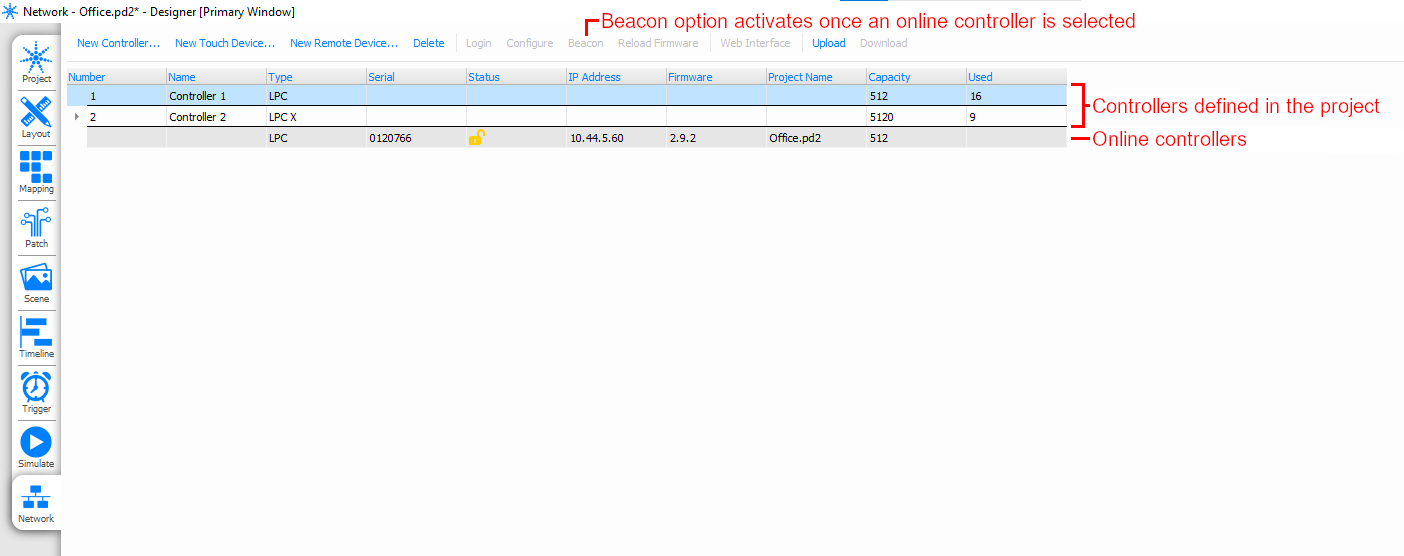
- Navigate to the "Network" page
- Select the Pharos controller from the list
- If a Pharos project is open, controllers defined in the project will be displayed above the list of online controllers
- If there are multiple online controllers, use the "Beacon" function to flash all the LEDs on the front of the controller and verify the correct one is selected
- If the Pharos Designer 2 version is different than the firmware on the Pharos controller, then it is necessary to either update the controller by pressing the "Reload Firmware" button, or downgrade Pharos Designer 2 by downloading the appropriate version from Pharos Controls' website
- Press the "Configure" button to open the network configuration menu
- Set DHCP mode to Static and configure the IP address, IP mask, default gateway, and DNS servers as required for your network
Once the Pharos controller is online, it is necessary to load the Pharos project to the controller:
- Open the Pharos project in Pharos Designer 2
- Connect to the network that the Pharos controller is on, or connect to the controller directly via USB
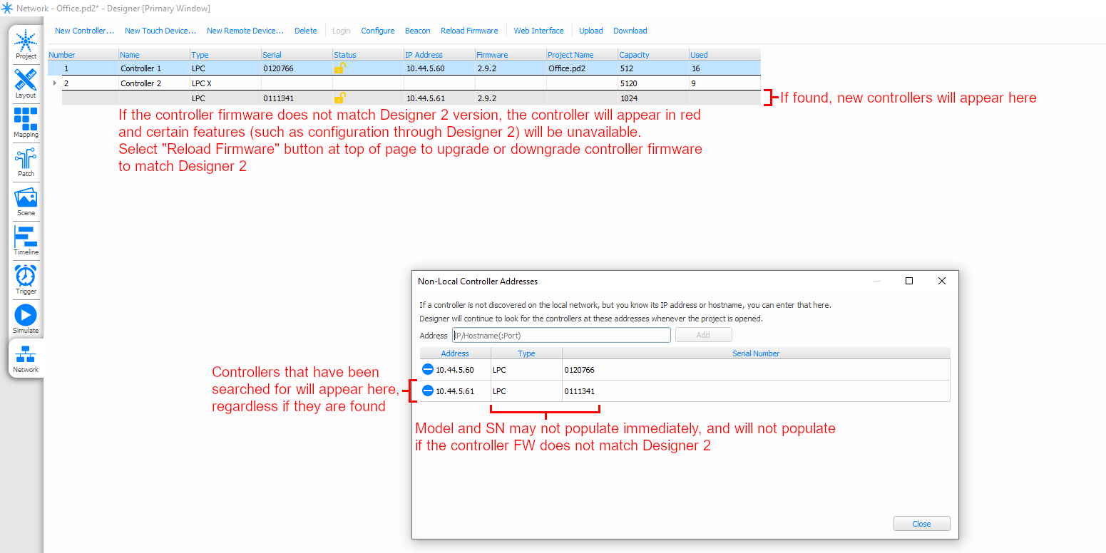
- Navigate to the "Network" page in Pharos Designer 2
- Verify that all online controllers have firmware that matches the version of Pharos Designer 2 you are running, and update them if necessary
- Online controllers are displayed below the list of controllers that are defined in the project
- If you do not see the controller online and you are hard-wired to the same network as the controller, verify that the controller has the correct IP settings
- If the controller is on a Control Subnet and you are connecting via the LAN, verify that port forwarding has been configured and proceed to the next step
- If you do not see the controller online, but you are connecting to it over a routed network, proceed to the next step
- Select a controller that is defined in the project
- In the Properties menu on the right, click the Serial Number dropdown menu and select the SN corresponding to the controller
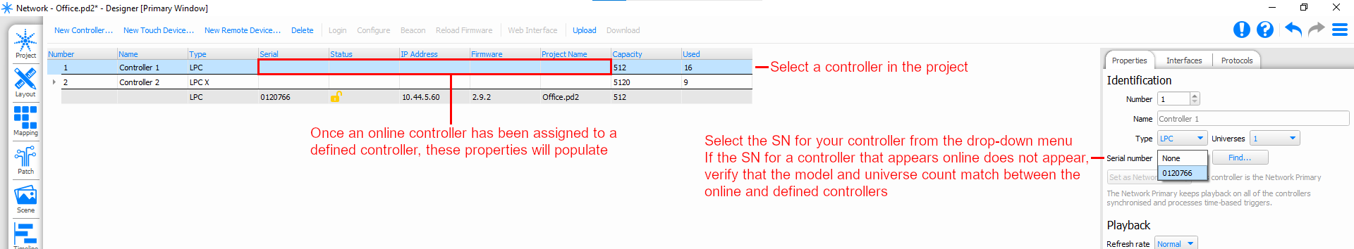
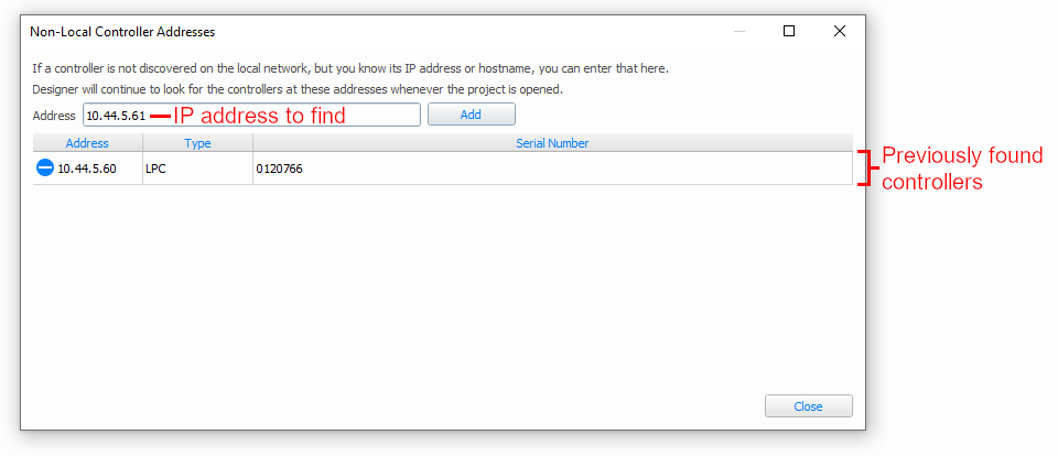
- If you do not see the corresponding serial number, click the "Find..." button to open the search menu
- If you are connecting to the controller over a routed network, put the controller's IP address into this field and press the "Add" button
- If you are connecting to a controller on a Control Subnet from the LAN side of the processor, put the processor's LAN IP address followed by a colon and the external port number that corresponds to internal port 38008 of the controller. See our FAQ for information
- If there are multiple controllers in the project, repeat step 6 for all controllers
- Once all controllers defined in the project have been assigned a serial number, press the "Upload" button
- Upload the project to individual controllers, or press the "Upload All" button to upload the project to all online controllers
Pharos projects can also be loaded to controllers using the web interface, but in these cases it is still necessary to assign the Serial Number of the controller to the controller that is defined in the Pharos project. Additionally, the Pharos project must be exported for upload. See our FAQ for details.
ShowRunner™ Configuration
ShowRunner™ is able to control fixtures in Pharos by sending group-level commands directly to Fixture Groups that are defined in the Pharos project, triggering Timelines that are defined in the Pharos project, or both. Note that ShowRunner™ does not receive feedback from the Pharos controller, so fixture feedback as shown in the ShowRunner™ UI is only accurate if ShowRunner™ sent group-level commands. Changes to fixture levels caused by a Timeline are not reflected in the ShowRunner™ UI. A video tutorial of setting up Pharos loads and configuring Scene Tracking is available on our YouTube channel.
In order to control DMX fixtures on a Pharos controller with ShowRunner™, it is necessary to make sure that the ShowRunner™ configuration has the correct settings for the Pharos controller. Under the "LightingControllers" section of the ShowRunner™ configuration, locate the entry for the Pharos controller. Under the "Properties" section, verify that the "IpAddressOrHostname" matches the IP address or hostname of the Pharos controller. The "ApiPort" only needs to be changed if the HTTP port for the Pharos controller's web server has been changed from the default 80. Once the Properties for all Pharos controllers have been updated, load the configuration to the processor.
Define Pharos Loads in ShowRunner™
Control Pharos groups with ShowRunner™, it is necessary to define them as loads in the ShowRunner™ configuration. To do this using the XPanel UI, navigate to the Settings > Load Configuration page and then select the Pharos controller from the list of controllers on the left. Once the controller is selected, press the "Configure Loads" button:
- Currently defined loads are shown in the list on the left
- The "Group: #" of the load must match the group number as defined in the Pharos project
- It is not possible to change the group of an existing load from the XPanel UI. Instead, either save the config and edit the "LoadBaseIndex" property of the load, or delete the load and create a new load at the correct group
- Press "Add New Load" below the list of loads to create a new load
- The "Load Index/Channel" must match the group number as defined in the Pharos project
- Since ShowRunner™ uses group-level commands and fixtures in a group aren't necessarily on the same DMX universe, the "Universe ID" is grayed out and cannot be modified
- It is not possible to assign multiple Pharos groups to the same load, and it is not possible to assign multiple loads to the same group
- To have a single load in ShowRunner™ control multiple Pharos groups, create a new group in the Pharos project that contains the other groups and then associate the ShowRunner™ load with the super-group
- To have multiple ShowRunner™ loads control the same set of fixtures, create multiple groups in the Pharos project and assign the same fixtures to all groups (this is useful e.g. to allow ShowRunner™ to control an HSIC fixture using either RGB or dynamic white without needing to change the Load Type)
- The "Load Type" does not need to strictly match the fixture type as defined in the Pharos project, as the Pharos controller will do its own processing to mix the DMX output to achieve the desired color
- "Single Channel" loads are interpreted by the Pharos as intensity only
- Fixture profiles with a dedicated channel for intensity (IRGB, HSI, HSIC, ICHS, etc.) will only adjust the intensity channel, leaving the color and color temperature unchanged
- Fixture profiles without a dedicated intensity channel (RGB, RGBA, RGBW, etc.) will set all channels to the same intensity value sent by ShowRunner™
- "Dynamic White" loads are interpreted by the Pharos as an intensity and a color temperature
- Fixture profiles with dedicated intensity and color temperature (HSIC, ICHS, I/CCT, etc.) will use the values sent by ShowRunner™
- Pharos will attempt to mix the DMX output for fixture profiles without dedicated intensity and color temperature channels (warm/cool, RGBW, etc.) in order to match the values sent by ShowRunner™
- "RGB" loads are interpreted by the Pharos as an intensity + specific red, green, and blue values
- Fixture profiles with a dedicated channel for intensity (IRGB, HSI, HSIC, etc.) will use the load level sent by ShowRunner™ for intensity and then mix the other channels to match the RGB values
- Fixture profiles without a dedicated intensity channel (RGB, RGBW, etc.) will mix the intensities for each color to attempt to match the color and overall intensity sent by ShowRunner™
- "Single Channel" loads are interpreted by the Pharos as intensity only
- If controlling the RGB and White channels of an RGBW fixture separately, then you must define an RGB type load associated with the RGB fixture group in Pharos and then a Single Channel type load associated with the White fixture group in Pharos
- The Area Assignment dictates what area the load will be associated with
- The "Load Index/Channel" must match the group number as defined in the Pharos project
Scene Mapping
ShowRunner™ is also capable of triggering Timelines in the Pharos project by mapping Pharos Timelines to ShowRunner™ Scenes. This can be configured using the XPanel UI:
- Navigate to Settings > Load Hardware
- Select the Pharos controller from the list of load controllers on the left
- Press "Configure Scene Tracking"
- Tick the "Enable Scene Tracking" box to enable scene tracking
- Select an area whose scenes you want to trigger Timelines from the "Area to Track" list
- Note that the area selected does not actually need any loads assigned to it
- Pharos fixture groups do not need to be defined as loads in ShowRunner™ at all if scene tracking is being used to control fixtures
- With the area selected, press "Add New Map"
- Select the scene you want to trigger the Timeline from the list of scenes
- Enter the number of the Timeline as defined in the Pharos project in the "Timeline ID" field
- Press "Add" to add the scene map
- Press "Add New Map" to add more Timelines, or select another area to trigger Timelines with scene recalls on other areas
Some things to consider if you are triggering Pharos Timelines with ShowRunner™:
- Since Scene Mapping will directly trigger Pharos Timelines, any Pharos fixture that is part of the Timeline will be affected
- Pharos Groups that are mapped to ShowRunner™ loads in other areas or Pharos Groups that are not defined in ShowRunner™ at all will still be affected if they are part of the Timeline
- If Scene Tracking is configured for a ShowRunner™ Area, the Pharos Timeline will be triggered regardless of whether any loads are assigned to the Area
- If Scene Tracking is configured for a ShowRunner™ Area, then recalling any Scene on the Area will release (stop) all Timelines that are associated with the Area before triggering any new Timelines associated with the Scene
- If the Scene being recalled does not have any Timeline associated with it, any Timelines associated with the area are still released
- Scene recalls are still executed even if Scene Tracking is enabled
- Non-DMX loads in an area with Scene Tracking will still go to their predefined scene levels unless they are excluded from the scene
- Pharos DMX loads will go to their predefined scene levels unless they are excluded from the scene, even if they are included in the Pharos Timeline being triggered
- If Timelines are being used to control DMX fixtures, then the Fixture Groups do not actually need to be defined in ShowRunner™ unless direct control of the Fixture Groups is desired
Fixture Addressing and Identification
Pharos Designer 2 has several features that make it relatively straightforward to address DMX fixtures, or to change how fixtures need to be addressed in order for the lighting controls to work correctly.
Re-Patching Fixtures
Since ShowRunner™ uses fixture groups to send commands to DMX fixtures on the Pharos LPC, the specific fixture universe and address does not matter as long as fixtures have been addressed according to the Pharos project. This means that if fixtures were installed and connected to a different universe than originally anticipated, it is relatively straightforward to re-patch fixtures to different addresses on different universes while maintaining their groups in the Pharos project without requiring changes to the ShowRunner™ configuration.
In order to re-patch fixtures in the Pharos project:
- Open the project in Designer 2 and navigate to the "Patch" page
- All fixtures and fixture groups in the project will appear in a hierarchical tree view on the left
- All fixtures are present, regardless of grouping or which layout they appear on
- Fixtures will appear multiple times: once in the "All Fixtures" section, and then again in any groups that they are assigned to
- Patched fixtures have blue text, even if they are not patched to the currently visible universe
- Unpatched fixtures have black text
- The currently selected fixture has red text regardless of whether it is patched or not
- Current patching is viewed on the screen to the right
- By default, all universes on all controllers are shown
- Displayed universes can be narrowed down by selecting controllers and outputs from the list of controllers
- The currently selected fixture is highlighted in red in the fixture list and in blue if it is patched to the currently visible universe
- All fixtures and fixture groups in the project will appear in a hierarchical tree view on the left
- There are two options to patch or re-patch fixtures
- Drag the fixture from the list of fixtures on the left and onto the universe on the right
- Select a previously patched fixture from the universe on the right and move it to a new address, or right-click to un-patch entirely
- When patching or re-patching fixtures, keep the following in mind:
- If there are controllers with multiple universes, or multiple controllers defined in the project, ensure that the fixtures are patched to the correct controller and universe
- Fixtures can be patched to multiple addresses, but it is not possible to patch multiple fixtures to the same address
- Fixtures can be unpatched by right clicking them in the universe
- Be wary of accidentally assigning fixtures to multiple groups when dragging them onto the universe to be patched
- Be sure to re-upload the project to all controllers if patching has been modified for an existing project
Remote Device Management
In addition to allowing the re-patching of fixtures, Pharos LPC have Remote Device Management (RDM) capabilities that allow for remotely addressing DMX fixtures provided the fixtures are RDM capable. More general information regarding DMX networks and methods for addressing non-RDM capable fixtures is available on our DMX Fixture Addressing page.
In order to perform RDM addressing in Pharos Designer 2:
- Ensure that the controller in the project you wish to address fixtures for has been assigned a live (currently online) controller and that the project has been uploaded to the live controller
- Open the project in Designer 2 and navigate to the "Patch" page
- Select the controller that you wish to address devices for
- Press the "Discover" button that corresponds to the output that you want to address devices for
- Single-universe LPCs have separate "Discover" buttons corresponding to each of the two DMX outputs
- Multi-universe LPCs and EDNs typically have a single "Discover" button for each universe, as there is a 1-to-1 relationship between the output and the universe
- A window will appear and list all discovered devices, along with a unique device ID, manufacturer/model information, personality (control mode), footprint (number of required addresses), and their current start address
- Due to manufacturer compatibility issues, some RDM-capable devices may not appear online, and available information (such as personality) may be incomplete for those devices that are online
- Non-driver devices (such as splitters) will appear in the list, but it will not be possible to change their start address
- In cases where RDM capable devices do not appear online, they must be addressed manually as described on our DMX Fixture Addressing page
- Click the "Identify" button and then select the device from the list of available devices in order to identify a specific RDM device
- The device should identify itself by flashing any attached loads (if a driver), or by flashing indicator LEDs (if it is another type of device, such as a splitter)
- To change a device's start address, double-click its start address and type the new start address
- Once all devices have been identified and re-addressed, click the "Discover" button to refresh the list and verify that no new devices appear online
- Repeat steps 3 through 8 for all controllers
- If discovering on all outputs of all controllers does not reveal all the expected drivers, then it may be necessary to manually address drivers as described on our DMX Fixture Addressing page and move on to troubleshooting the DMX installation
Address Verification
Once fixtures have been addressed, they can be verified using the ordinary ShowRunner™ load verification processes and tools. If fixtures are not behaving as expected, then it may be necessary to dig deeper and determine where the issue lies. To rule out or identify load configuration issues in ShowRunner™, first verify that fixtures are patched and grouped correctly in the Pharos project, and that the loads in ShowRunner™ are mapped to the correct groups in Pharos.
If the Pharos project and ShowRunner™ configuration are determined to be in sync, then the next step is to verify that fixtures have been addressed correctly:
- Ensure that the controller in the project you wish to address fixtures for has been assigned a live (currently online) controller and that the project has been uploaded to the live controller
- Open the project in Designer 2 and navigate to the "Layout" or "Patch" page
- (Layout page shown, but both pages have this capability)
- Click the lightbulb icon on the top of the page
- Select a fixture to begin flashing fixtures in the field
- Fixtures or entire fixture groups can be selected from the fixture hierarchy on the left
- On the Layout page, fixtures can also be selected from the layout
- On the Patch page, fixtures can be selected
- If the wrong fixtures flash when the fixture or fixture group is identified in Pharos, then there is an issue with how the fixtures are addressed or patched
- If the expected fixtures (and only the expected fixtures) flash when identified in Pharos, then fixtures have been addressed correctly
- To stop identifying selected fixtures, click the lightbulb icon again
The Pharos web UI can also be used as an alternative to Designer 2 in order to verify fixture addressing by parking and unparking individual channels from the "Output" tab. This method also enables you to verify that the correct fixture profiles have been assigned in the Pharos project by comparing the fixture behavior when individual channels are parked to the expected behavior based on the assigned fixture profile:
- Ensure that a project is loaded to the controller and then connect to it by entering the IP address into a web browser
- If you are connecting to a controller on a Control Subnet from the LAN side of the processor, input the processor's IP address along with the appropriate port. See our FAQ for information
- Navigate to the "Output" tab to see live outputs
- At the top of the page, select the appropriate universe for controllers with multiple universes
- All 512 channels in the selected universe
- Channels with fixtures patched to them appear in white, along with current output level
- Channels with no fixtures patched to them appear in gray
- Channels that are currently parked (overridden) appear in red
- Channels that are currently being used in a timeline or Pharos scene appear in yellow
- In the "Park" section at the bottom, use the "Channels" and "Level" fields to override specific channels to a specific level
- Use commas and hyphens to select multiple or ranges of addresses
- Leaving the "Level" section blank will park the channels at 0
- Use tab, shift-tab, and enter to quickly navigate between and confirm fields in the "Park" and "Unpark" sections
- In the "Unpark" section at the bottom, use the "Channel" field to release currently parked channels
- Use commas and hyphens to select multiple or ranges of addresses to unpark
- Use tab, shift-tab, and enter to quickly navigate between and confirm fields in the "Park" and "Unpark" sections
- Parking channels is useful to verify fixtures have been addressed correctly
- Parking all channels at 0 and then parking individual channels or ranges of channels at 255 helps to verify that fixtures are addressed correctly and that there are not multiple fixtures that have been accidentally addressed alike
- Parking all of a fixture's channels at 0 and then individually parking individual channels at 255 helps to verify that the start address is correct and that the fixture type assigned in the project (RGBW, HSIC, IRGB, etc.) matches the actual behavior of the fixture
- Always un-park all channels before disconnecting, as parked channels will not be affected by Pharos timelines and will not be controllable from ShowRunner™