Phase Dimming Troubleshooting
Phase dimming is one of the most common dimming methods for LED fixtures. The term "phase dimming" actually encompasses several dimming technologies which all operate on the same basic principal of chopping up the AC voltage being delivered to the fixtures or drivers.
Phase dimming can be broadly divided into two categories: forward phase dimming and reverse phase dimming. Forward phase dimming operates by cutting off the front (leading edge) of the AC sine wave, while reverse phase dimming cuts off the back (trailing edge) of the AC sine wave. See the real world data below for an illustration.
In the event that phase dimming fixtures are exhibiting unexpected dimming behavior, an easy place to begin troubleshooting is at the lighting control module.
Verifying Module Output
Crestron produces a variety of phase dimming lighting controllers, and the specifics for troubleshooting them varies slightly. That being said, there is a general procedure for testing phase dimming modules that is applicable to any type of phase dimming controller (even non-Crestron controllers). This general procedure is as follows:
- Identify the module and output that should be dimming the fixtures
- Disconnect the switch leg to the fixture
- Connect a multimeter to the switch leg output of the module
- Measure the V AC output at various brightness levels
- If the system has been partially or fully commissioned, it may be possible to use the ShowRunnerCLC™ UI to adjust the brightness
- Alternatively, some modules have physical buttons that can be used to adjust their brightness:
- Press the button to toggle the output on or off. A small LED light on the module will indicate current output on/off status.
- Once the output is on, press and hold the button to cycle dim the output (first press and hold will lower the output, subsequent press and holds will toggle between raising and lowering the output)
- The measured V AC should decrease with lower brightness levels, but does not necessarily have a linear relationship to the brightness (e.g., output at 20% brightness will be a lower voltage than at 100% brightness, but will not necessarily be 20% of the voltage).
- Chief Integrations has recorded actual AC outputs for a few different 120V Crestron modules, available at the bottom of this article.
Verifying Fixture Wiring and Compatibility
Troubleshooting Phase Dimming Wiring
There are a number of wiring and hardware issues that may result in fixtures not behaving as expected. If fixtures are flickering rapidly as they are dimmed, then fixture compatibility with the dimming module should be verified. Check for incorrect wiring in the field by powering off the circuit for the fixtures, disconnecting the wiring from the module to the fixtures, and then powering the circuit back up. If the wires going to the fixtures still have voltage on them, then they are receiving power from some other source besides the module, which will result in dimming and control issues.
Determine Fixture Compatibility
If the fixtures are misbehaving but the wiring has been verified correct, then there may be compatibility issues between the fixture, the driver, and the lighting controller.
Crestron maintains a list of compatible drivers on their website. Determine the fixture and driver that have been installed and verify they are compatible with the phase dimming lighting controller being used.
Verify that the LED drivers are actually phase dimming drivers and not 0-10V, non-dimming, DALI, or some other dimming drivers. If the drivers are not phase dimming control drivers, then it will not be possible to dim the fixtures using a phase dimming module unless the drivers are changed out for phase dimming drivers.
Verify that the type of phase dimming required (forward or reverse) matches the type of phase dimming being output by the module. Many Crestron modules are universal phase dimming which should auto-detect the required dimming, but sometimes it will detect the incorrect dimming and must be forced to the correct mode. Consult the installation guide for each module to determine how to check and force the dimming mode.
It is also possible that there is a compatibility issue between the LED driver and the fixture. There are two types of LED driver: constant current and constant voltage. Constant current drivers dim the LED fixtures by varying the voltage output to reduce power while keeping current constant. Constant voltage drivers dim the LED fixtures by rapidly pulsing a constant voltage output. If the incorrect type of driver is used to power the fixtures (e.g. a constant current driver used for fixtures which require constant voltage), then the fixtures will not dim correctly. Verify that the drivers used are compatible with the fixtures.
Specific Crestron Modules
The below sub-sections cover specific dimming procedures for various phase dimming controllers produced by Crestron.
CLX-2DIMU8 and CLX-2DIMU8-277
Phase dimming CLX modules are installed inside CAEN panels, which are typically located inside an electrical room or an MDF/IDF closet.
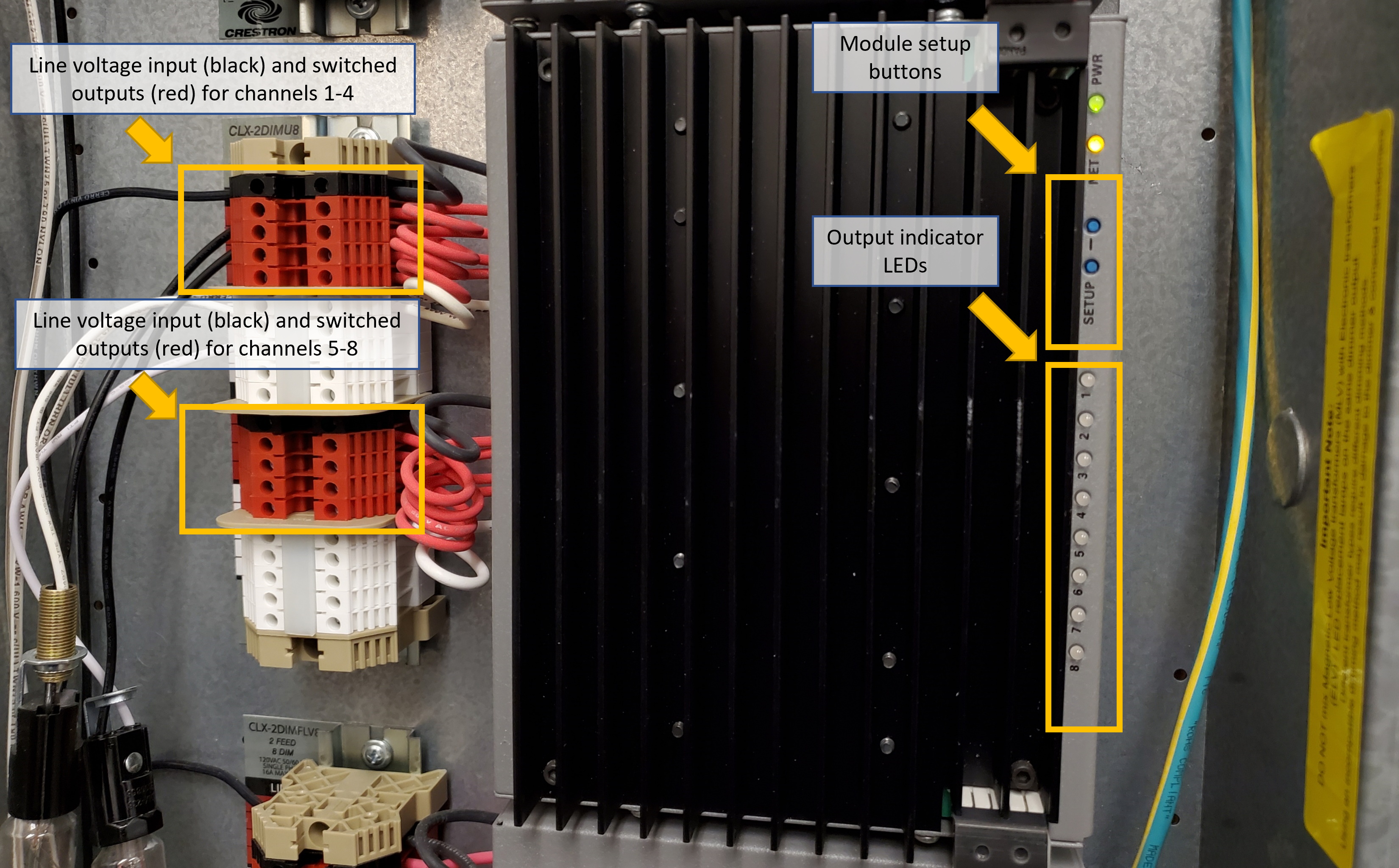
Each CLX module has eight outputs split into two groups: outputs 1 through 4 are in the first group, while outputs 5 through 8 are in the second group. Even if there are no loads in the first group of outputs, the module still requires a line voltage input in order to function. The second group of loads will appear to be able to be toggled on and off, but the outputs will not change unless the second group of outputs is receiving a line voltage input. The line voltage input for the second group of outputs does not need to be on the same circuit as the line voltage input for the first group, but it must be on the same phase.
On the front of 0-10V CLX modules are eight LEDs corresponding to each of the eight outputs. Above these LEDs are two buttons which can be used to toggle each output individually, view the current dimming mode, and switch the dimming mode for each output. There is no way to dim individual outputs from the module; the system must be at least partially commissioned with a functioning processor in order to verify dimming functionality.
See Figure 1 for details.
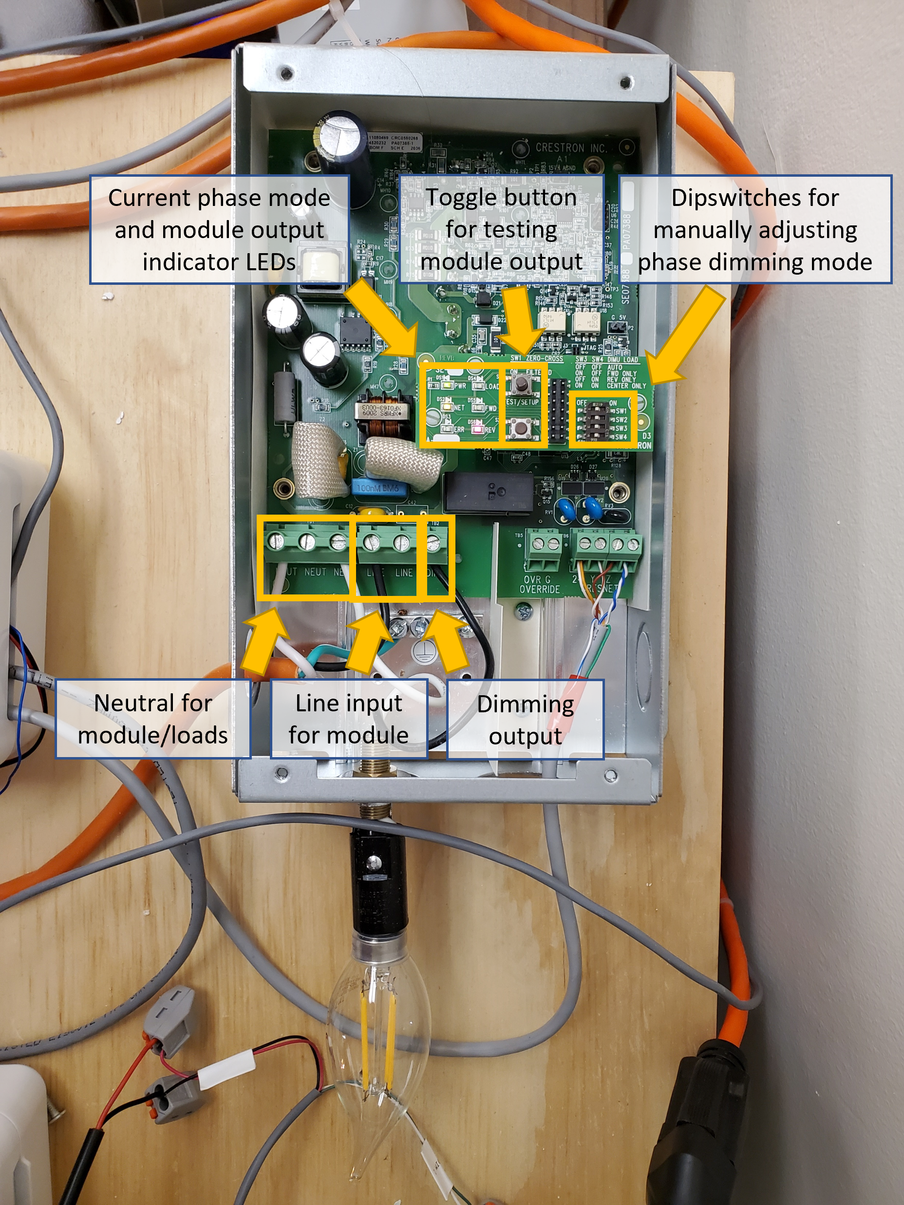
GL-EXP-DIMU-CN
GL-EXP-DIMU-CN are single-channel expansion modules used to provide additional phase dimming control to a system. They are self-contained and are surface mounted directly to a wall or ceiling.
LEDs on the module face indicate the current phase dimming mode, while dip-switches inside the module can be used to force the module into either forward or reverse phase dimming mode.
In order to access the phase dimming output, the front of the module must be removed. Inside the module is a paper barrier separating the high voltage output (on the left) from the low voltage control wiring (on the right). A small flathead screwdriver is required to disconnect the high voltage wiring to the fixtures.
The "ON/OFF" light on the front of the module indicates the current output status (red means the output is on), and the button next to it can be used to toggle the output on or off. Press and hold the button to cycle dim the phase dimming output.
The ON/OFF button sits proud of the module cover, so care must be taken when replacing the cover to avoid damaging the button.
See Figure 2 for details.
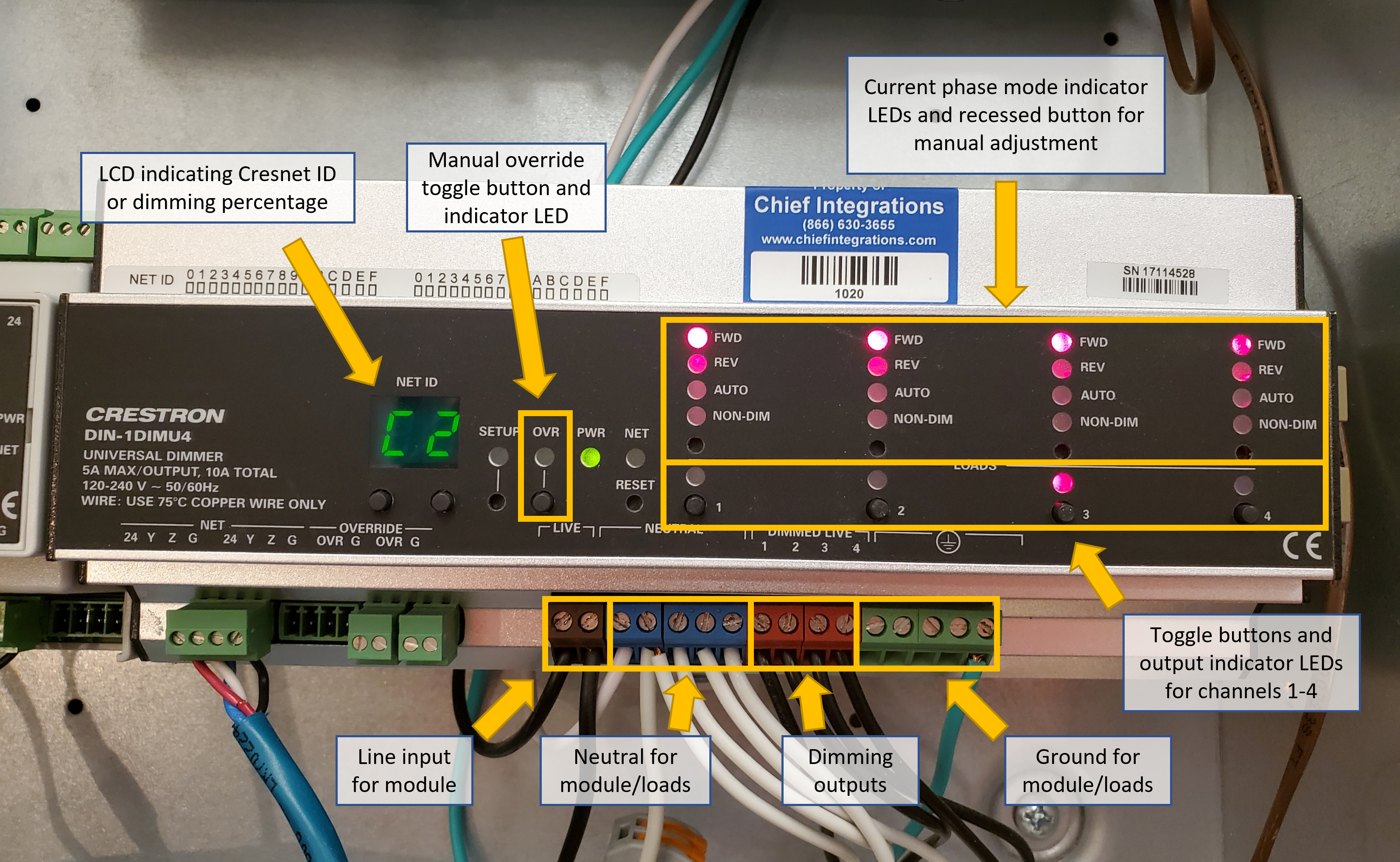
DIN-1DIMU4
Phase dimming DIN-1DIMU4 modules are installed inside DIN panels, which are typically located inside an electrical room or an MDF/IDF closet.
Each DIN-1DIMU4 module has four dimming outputs which all share a common line input. Each output has an LED to indicate current output status (on or off) and a button that can be used to toggle the output. Press this button once to turn the load on or off, and then press and hold this button to raise or lower the output. While dimming, the output percentage is indicated on the LCD screen on the module. Above the toggle button and load indicator LED, each output also has LEDs to indicate current phase dimming mode. Available phase dimming modes are: forced forward, forced reverse, auto-detect, and non-dim (switched). When in auto-detect mode, the "Auto" LED will be lit alongside either the "FWD" or "REV" LED to indicate which type of dimming has been detected. Below the phase mode LEDs is a recessed button which can be pressed to cycle between available phase dimming modes.
See Figure 3 for details.
Real World Phase Dimming Data
Below is a table of actual phase dimming readings at various percentage brightness for some Crestron lighting controllers. Measurements were taken from 120V modules using a true-RMS meter (note that the oscilloscope graph appears high because it is reading the peak voltage).
| Percentage Brightness | CLX-2DIMU8 Oscilloscope Output | CLX-2DIMU8 Reading (Reverse Phase) | CLX-2DIMU8 Reading (Forward Phase) | GL-EXP-DIMU-CN Reading (Reverse Phase) |
|---|---|---|---|---|
| 100% | 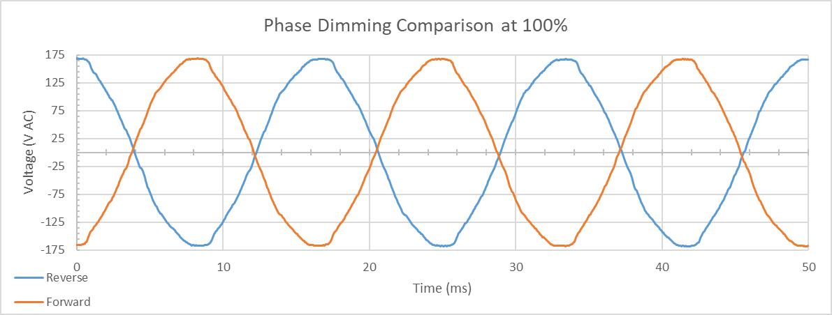 | 119.7 V AC | 119.7 V AC | 120.4 V AC |
| 80% | 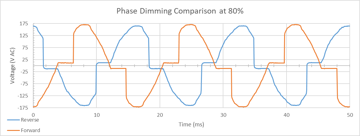 | 112.7 V AC | 110.5 V AC | 113.8 V AC |
| 60% | 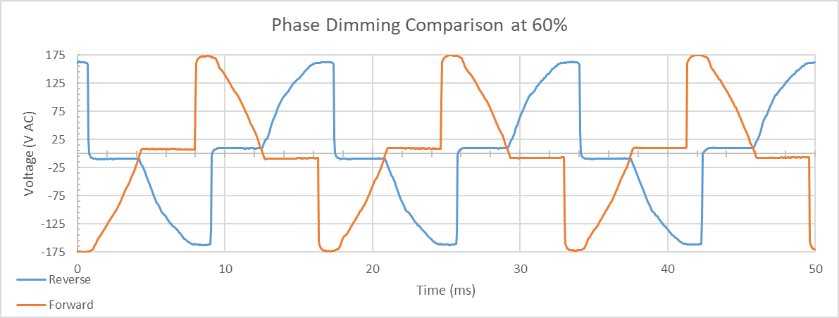 | 98.5 V AC | 95.4 V AC | 99.1 V AC |
| 50% | 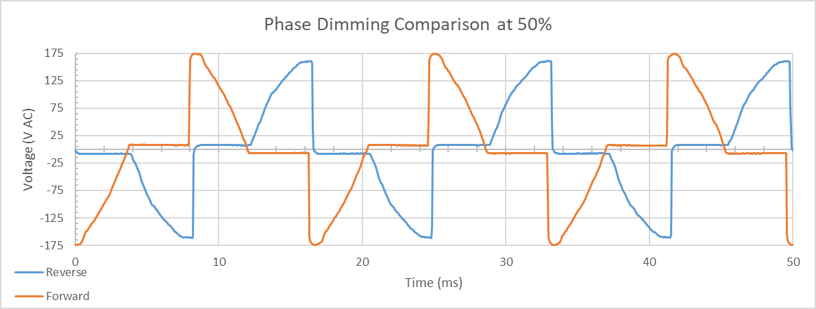 | 87.2 V AC | 86.0 V AC | 90.5 V AC |
| 40% | 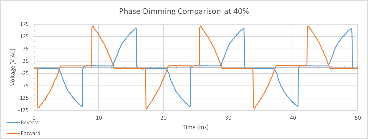 | 75.2 V AC | 71.5 V AC | 78.1 V AC |
| 20% | 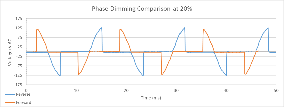 | 47.5 V AC | 43.6 V AC | 52.72 V AC |
| 0% | 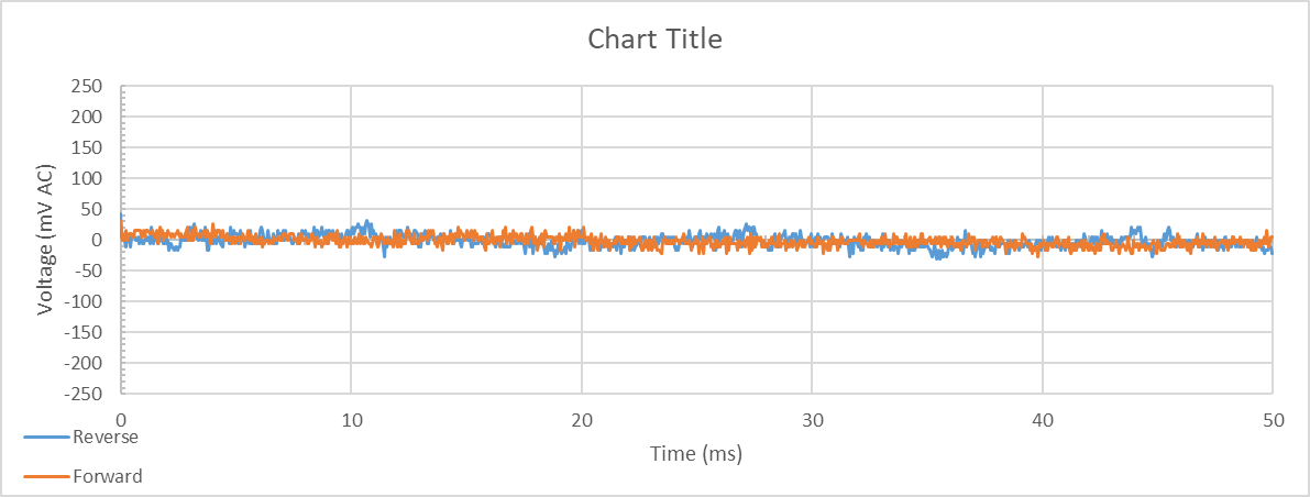 | 0.003 V AC | 0.004 V AC | 1.209 V AC |