0-10V Dimming Troubleshooting
0-10V dimming is one of the most common dimming methods for LED fixtures. It utilizes a 0-10VDC signal from the lighting controller to the fixture power supply or driver in order to control the brightness of the fixtures. This 0-10VDC signal is typically carried over a shielded pair of gray (negative) and violet (positive) wires. In the event that 0-10V dimming fixtures are exhibiting unexpected dimming behavior, an easy place to begin troubleshooting is at the lighting control module.
Verifying Module Output
Crestron produces a variety of 0-10V lighting controllers, and the specifics for troubleshooting them varies slightly. That being said, there is a general procedure for testing 0-10V dimming modules that is applicable to any type of 0-10V controller (even non-Crestron controllers). This general procedure is as follows:
- Identify the module and output that should be dimming the fixtures
- Disconnect the 0-10V wiring to the fixtures
- Connect a multimeter to the 0-10V dimming output of the module
- Measure the 0-10V output at various brightness levels
- If the system has been partially or fully commissioned, it may be possible to use the ShowRunnerCLC™ UI to adjust the brightness
- Alternatively, some modules have physical buttons that can be used to adjust their brightness:
- Press the button to toggle the output on or off. A small LED light on the module will indicate current output on/off status.
- Once the output is on, press and hold the button to cycle dim the output (first press and hold will lower the output, subsequent press and holds will toggle between raising and lowering the output)
- The 0-10V output should roughly correspond to the percentage brightness, e.g. a 60% bright output should be approximately 6V DC
- Chief Integrations has recorded actual 0-10V outputs for a few different Crestron modules, available at the bottom of this article.
Below is a table of how to interpret troubleshooting results:
| Result | Interpretation | Next Steps |
| Module produces the expected 0-10V DC output while fixtures are disconnected. | Module is not defective. The issue is likely with 0-10V wiring in the field or with LED fixture drivers. | Proceed to troubleshooting the fixture wiring and fixture compatibility. |
| Module does not produce a steady 0-10V signal while fixtures are disconnected. | Module or control wiring may be defective. | Disconnect the lighting controller from the processor and repeat the 0-10V troubleshooting procedure in order to eliminate the possibility of programming being the issue.
|
Verifying Fixture Wiring and Compatibility
Troubleshooting 0-10V Wiring
There are a number of wiring and hardware issues that may result in fixtures not behaving as expected. Described below are some techniques that can help determine issues with wiring or hardware, however due to the wide variety of available fixtures and drivers it is not comprehensive.
- Identify the module and output that should be controlling the fixtures
- Disconnect the 0-10V wiring to the fixtures
- Toggle the module output on and off to verify it is switching the correct zone
- If the system has been partially or fully commissioned, it may be possible to use the ShowRunnerCLC™ UI to toggle the module output
- Alternatively, some modules have physical buttons that can be used to toggle the output:
- Press the button to toggle the output on or off. A small LED light on the module will indicate current output on/off status.
- Once the output is on, press and hold the button to cycle dim the output (first press and hold will lower the output, subsequent press and holds will toggle between raising and lowering the output)
- While the fixtures are turned off, verify that the voltage on the 0-10V wiring to the fixtures is close to 0 V
- While the fixtures are turned off, check the 0-10V wiring to the fixtures for shorts
- While the fixtures are turned on, verify that the voltage on the 0-10V wiring to the fixtures is close to +10 V DC
- While the fixtures are turned on, short the positive and negative dimming wires to the fixtures
- Most drivers will dim to 50% brightness, though some fixtures will turn off
- Reconnect the 0-10V wiring to the fixtures to the module output
- Verify the module output voltage while the fixtures are connected
- The module output should be similar to the module output while the fixtures are disconnected
Below is a table of how to interpret troubleshooting results:
| Result | Interpretation | Next Steps |
| 0-10V wiring to the fixtures reads -10V DC while fixtures are turned on and disconnected from the control module. | Positive and negative 0-10V wiring is reversed in the field at all drivers. | Reconnect the 0-10V wiring to the module output with reversed polarity (i.e. land violet wire to the field on the negative 0-10V output and land gray wire to the field on the positive 0-10V output) and check dimming again. |
| Intentionally shorting the 0-10V wiring to the fixtures while they are turned on does not affect their brightness | 0-10V wiring to the field is likely already shorted. | Find where the short is in the 0-10V wiring. |
When the 0-10V dimming wires are connected to the module, the module dims different fixtures than it toggles. Or; Intentionally shorting the 0-10V wiring to the fixtures while they are turned on dims different fixtures. | 0-10V wiring zones are mixed up in the field (e.g. multiple zones have their 0-10V wiring tied together, or the 0-10V wiring for two zones got swapped) | Determine whether the 0-10V wiring for the fixtures was simply landed at the incorrect output or if the wiring is incorrect in the field and then correct the wiring.
|
Determine Fixture Compatibility
If the fixtures are misbehaving but the wiring has been verified correct, then there may be compatibility issues between the fixture, the driver, and the lighting controller.
Crestron maintains a list of compatible drivers on their website. Determine the fixture and driver that have been installed and verify they are compatible with the 0-10V lighting controller being used.
Verify that the LED drivers are actually 0-10V drivers and not phase dimming, non-dimming, DALI, or some other dimming drivers. If the drivers are not 0-10V control drivers, then it will not be possible to dim the fixtures using a 0-10V module unless the drivers are changed out for 0-10V drivers.
There are two types of 0-10V LED driver: constant current and constant voltage. Constant current drivers dim the LED fixtures by varying the voltage output to reduce power while keeping current constant. Constant voltage drivers dim the LED fixtures by rapidly pulsing a constant voltage output. If the incorrect type of driver is used to power the fixtures (e.g. a constant current driver used for fixtures which require constant voltage), then the fixtures will not dim correctly. Verify that the drivers used are compatible with the fixtures.
Specific Crestron Modules
The below sub-sections cover specific dimming procedures for various 0-10V controllers produced by Crestron.
ZUMNET-JBOX-16A-LV and ZUMLINK-JBOX-16A-LV
Zūm Wired JBOXs mount to a 1/2" knockout of a standard junction box.
Inside the junction box will be two flying leads for the 0-10V dimming output. The grey lead is for the negative output and the violet lead is for the positive output. These leads should be wire nutted or lever nutted with the wiring to the fixtures. The leads should disconnected from the fixtures during troubleshooting.
On the front of the Zūm JBOX-16A-LV (outside the junction box) are two or three LEDs next to a black button. The LED labeled "TEST" will be green if the output is hot. The black button can be used to toggle the output on or off, and holding the button will cycle dim the 0-10V output.
See Figure 1 for details.
CLX-2DIMFLV8 and CLX-2DIMFLV8-277
0-10V CLX modules are installed inside CAEN panels, which are typically located inside an electrical room or an MDF/IDF closet.
Each CLX module has eight outputs split into two groups: outputs 1 through 4 are in the first group, while outputs 5 through 8 are in the second group. Even if there are no loads in the first group of outputs, the module still requires a line voltage input in order to function. The second group of loads will appear to be able to be toggled on and off, but the outputs will not change unless the second group of outputs is receiving a line voltage input. The line voltage input for the second group of outputs does not need to be on the same circuit as the line voltage input for the first group, but it must be on the same phase.
On the front of 0-10V CLX modules are eight buttons corresponding to each of the eight outputs. Next to each button is a red LED indicating the current load status. The LED will be lit if the output is on. To the right of the LED is the 0-10V output for each channel, which can be easily unplugged for troubleshooting. The buttons can be used to toggle each channel independently, and holding the button will cycle dim the 0-10V output for that channel.
See Figure 2 for details.
GL-EXP-DIMFLV-CN
GL-EXP-DIMFLV-CN are single-channel expansion modules used to provide additional 0-10V control to a system. They are self-contained and are surface mounted directly to a wall or ceiling.
In order to access the 0-10V output, the front of the module must be removed. Inside the module is a paper barrier separating the high voltage switched output and 0-10V dimming (on the left) from the low voltage control wiring (on the right). A small flathead screwdriver is required to disconnect the 0-10V wiring to the fixtures.
The "ON/OFF" light on the front of the module indicates the current output status (red means the output is on), and the button next to it can be used to toggle the output on or off. Press and hold the button to cycle dim the 0-10V output.
The ON/OFF button sits proud of the module cover, so care must be taken when replacing the cover to avoid damaging the button.
GLPP-DIMFLVCN-PM, GLPP-1DIMFLV2CN-PM, and GLPP-1DIMFLV3CN-PM (Discontinued)
GLPPs mount to two 4" junction boxes. The left junction box has low-voltage wiring for Cresnet and sensors, while the right junction box has high-voltage wiring to the fixtures.
Inside the right junction box will be at least two flying leads for the 0-10V dimming output. The grey lead is for the negative output. Depending on the module, there will be one or more violet leads for the positive output. Each lead will be labeled "DIM OUT #" to indicate which output they correspond to. These leads should be wire nutted or lever nutted with the wiring to the fixtures. The leads should disconnected from the fixtures during troubleshooting.
There are no manual controls on the GLPP that allow for dimming the output. GLPPs can only be dimmed through the lighting UI or with the use of a GLPPA-REMOTE-PROG programming remote. If using a remote to dim the outputs, the remote must have line of site with the IR receiver on the front of the GLPP. The GLPP remote has four columns of buttons; columns 1 through 3 contain separate ON/OFF, raise, and lower buttons for individual outputs. The fourth column contains these same buttons, but will control all outputs simultaneously.
One common source of dimming issues with multi-channel GLPPs is mixing up the switched outputs and the dimming outputs; fixtures should have their 0-10V dimming connected to the dimming output associated with the switched output that controls them.
GLPAC-DIMFLV4 and GLPAC-DIMFLV8 (Discontinued)
GLPAC modules are self contained and typically installed above the ceiling in the room they control.
Each GLPAC module has either four or eight outputs depending on the model. Each output has its own line voltage input. Even if there are no loads on the first output, the GLPAC still requires a line voltage input in order to function. The line voltage input for subsequent outputs do not need to be on the same circuit as the line voltage input for the first output, but they must be on the same phase.
On the front of the GLPAC are either four or eight buttons corresponding to each of the outputs. Next to each button is a green LED indicating the current load status. The LED will be lit if the output is on. The buttons can be used to toggle each channel independently, and holding the button will cycle dim the 0-10V output for that channel.
The 0-10V outputs are located on the top right of the module. A small screwdriver is required to disconnect the dimming to the fixtures.
See Figure 3 for details.
GLXP-DIMFLV8 (Discontinued)
0-10V GLXP modules are installed inside GLEP panels, which are typically located inside an electrical room or an MDF/IDF closet.
Each GLXP-DIMFLV8 module has eight outputs, each with its own line voltage input. Even if there are no loads on the first output, the GLXP still requires a line voltage input in order to function. The line voltage input for subsequent outputs do not need to be on the same circuit as the line voltage input for the first output, but they must be on the same phase.
On the front of GLXP modules are eight buttons corresponding to each of the eight outputs. Next to each button is a green LED indicating the current load status. The LED will be lit if the output is on. The buttons can be used to toggle each channel independently, and holding the button will cycle dim the 0-10V output for that channel. When dimming, the LCD "NET ID" screen will indicate the current expected brightness level.
The 0-10V outputs are split into the eight negative outputs and the eight positive outputs on the lower left of the module. A small screwdriver is required to disconnect the dimming to the fixtures.
See Figure 4 for details.
Real World 0-10V Data
Below is a table of actual 0-10V readings at various percentage brightness for some Crestron lighting controllers:
| Percentage Brightness | GLPP-1DIMFLV2CN-PM Reading | GLPAC-DIMFLV8 Reading | GLXP-DIMFLV8 Reading |
|---|---|---|---|
| 100% | 9.94 V | 10.03 V | 10.00 V |
| 80% | 8.02 V | 8.09 V | 8.08 V |
| 60% | 5.96 V | 6.13 V | 6.11 V |
| 50% | 4.98 V | 5.10 V | 5.04 V |
| 40% | 4.01 V | 4.06 V | 4.02 V |
| 20% | 1.98 V | 2.09 V | 2.06 V |
| 0% | 27.1 mV | 33.2 mV | 25.4 mV |
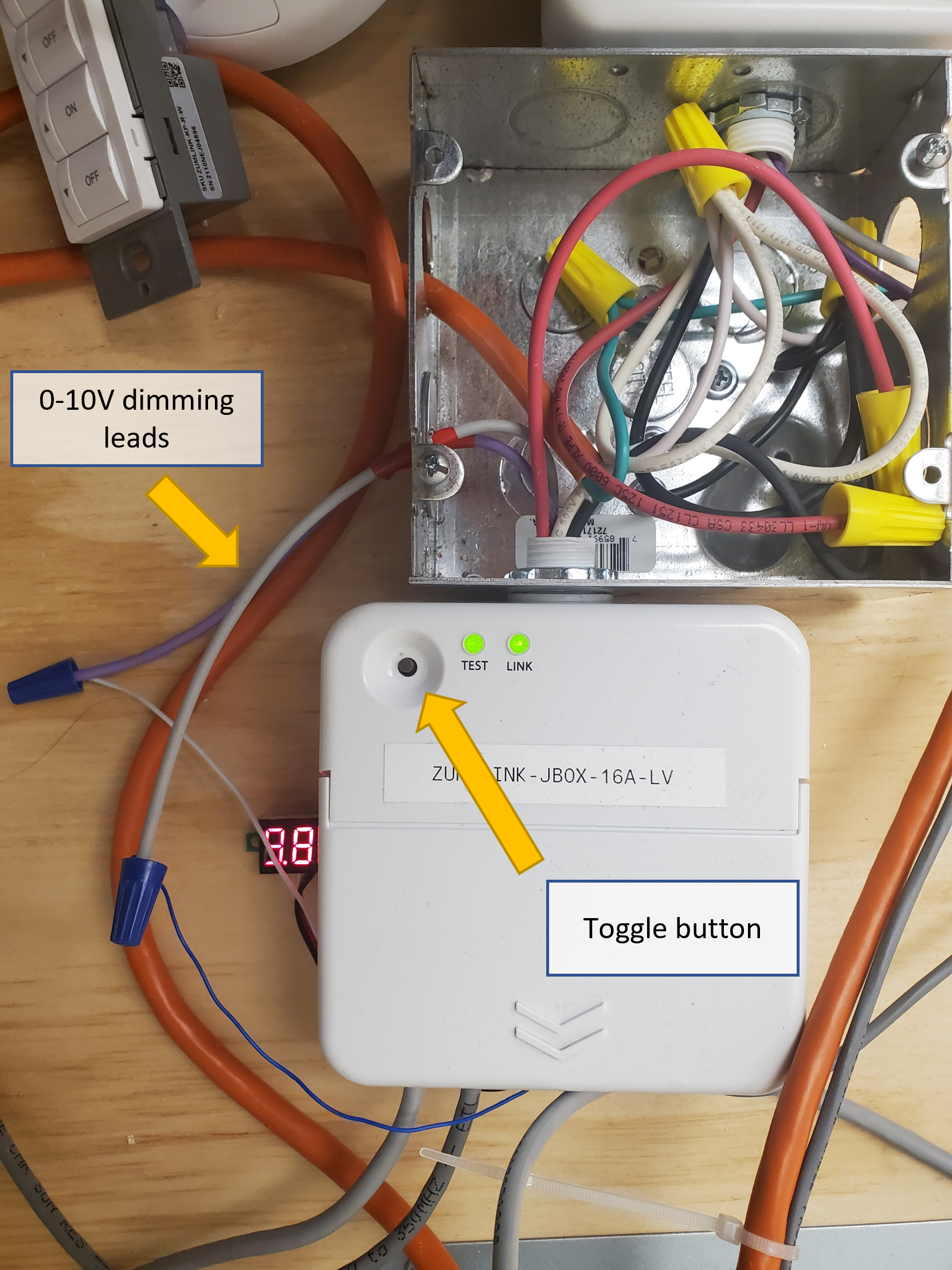
Figure 1: ZUMLINK-JBOX-16A-LV Overview (larger)
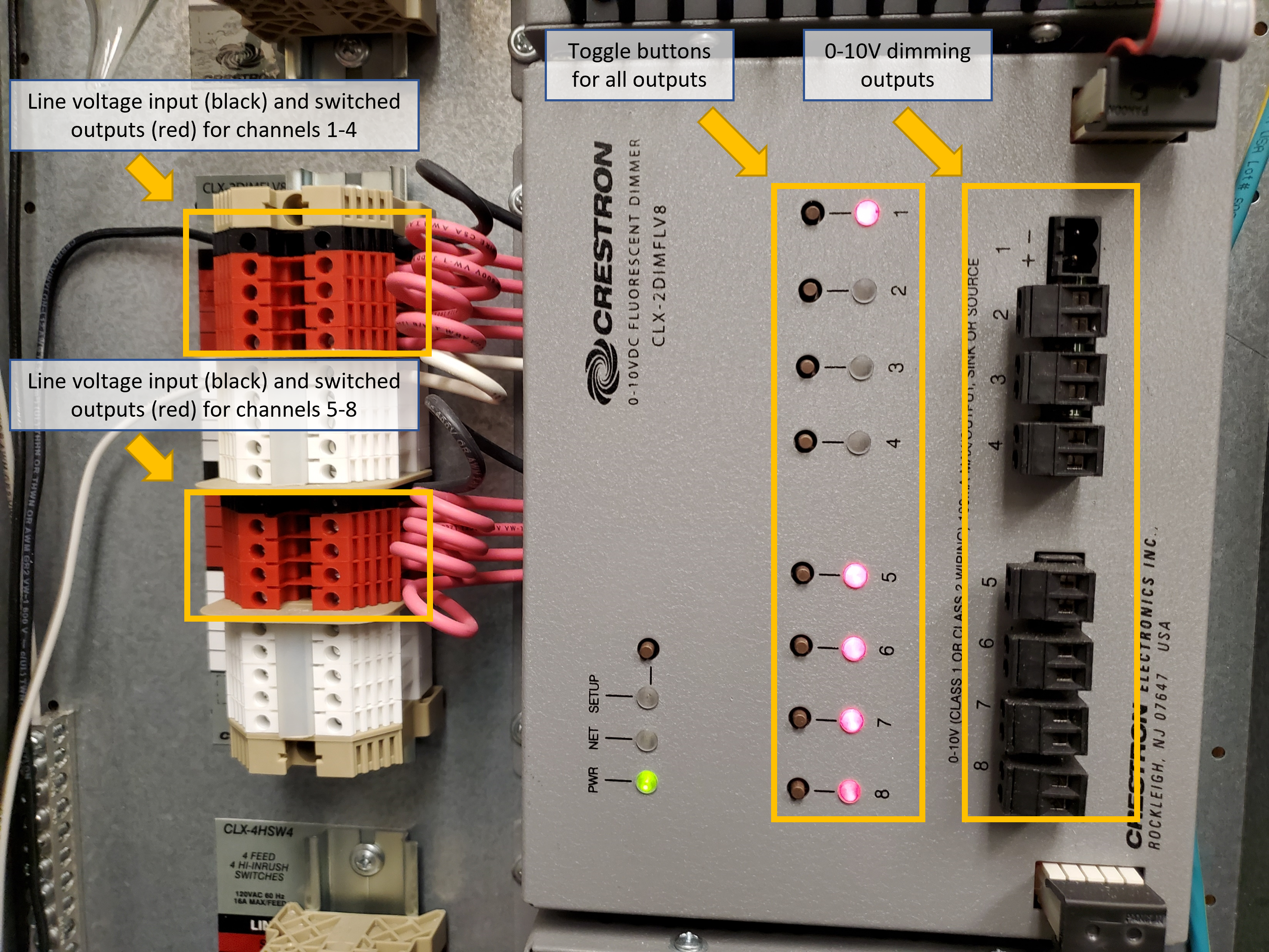
Figure 2: CLX-2DIMFLV8 Overview (larger)
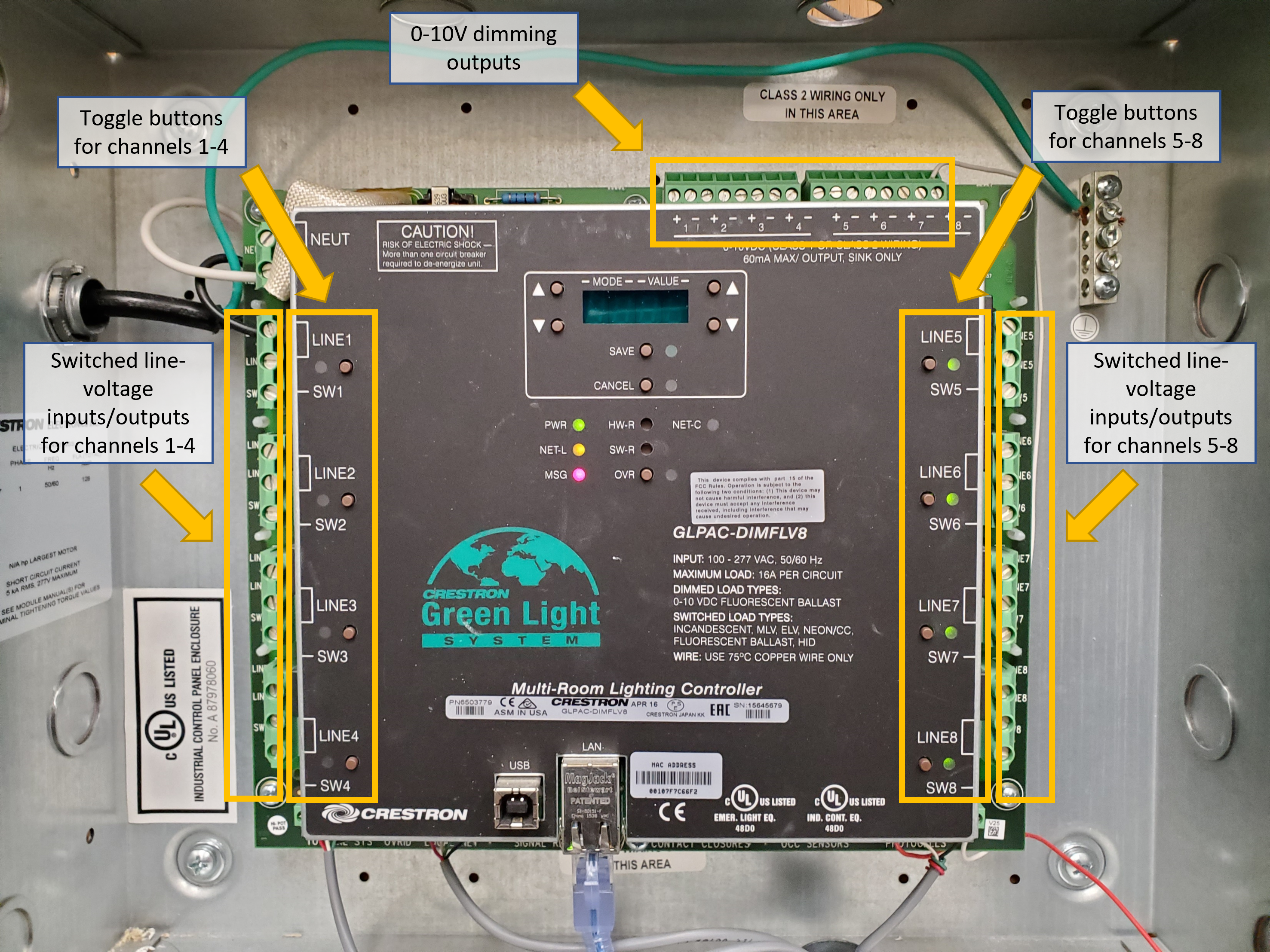
Figure 3: GLPAC-DIMFLV8 Overview (larger)
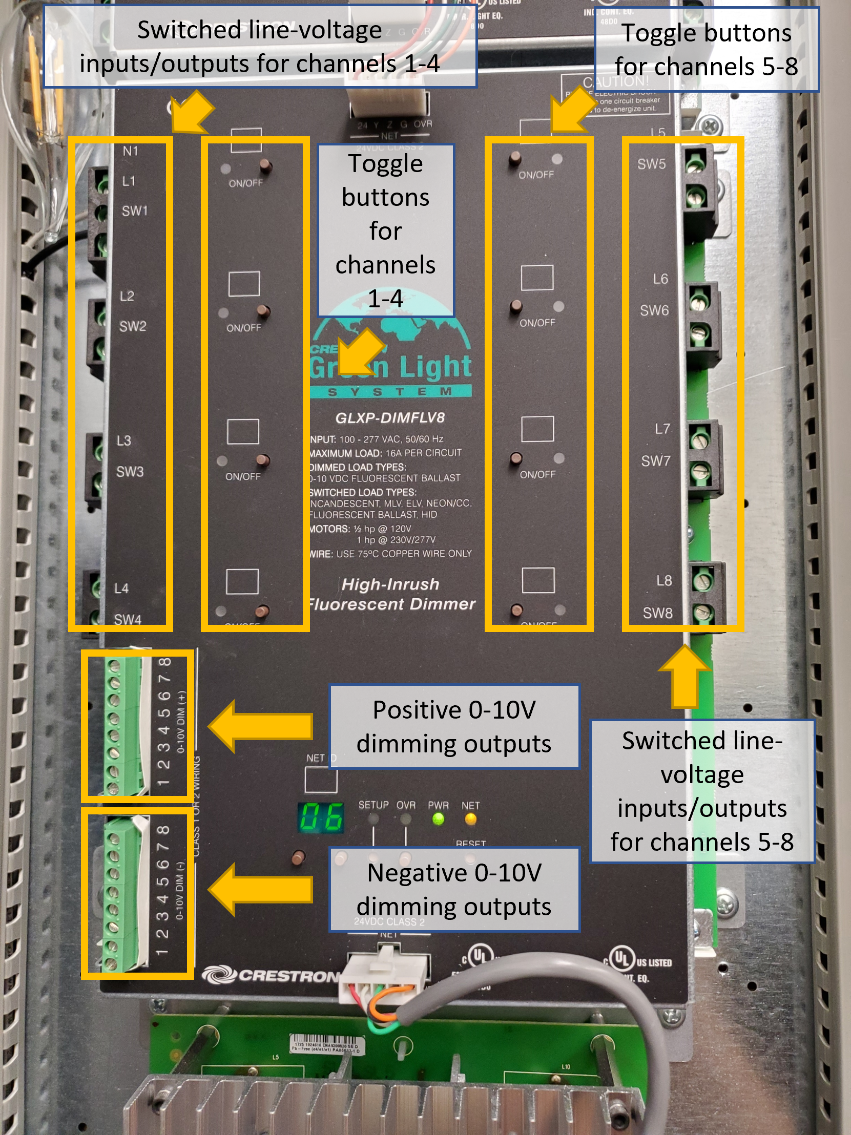
Figure 4: GLXP-DIMFLV8 Overview (larger)